Slotless winding for rotating electric machine and manufacturing method thereof

a technology of rotating electric machines and manufacturing methods, which is applied in the direction of windings, printed circuit aspects, printed electric component incorporation, etc., can solve the problems of disadvantageous mass production assembly and complex processes of above two methods, and achieve the effects of improving production speed and reliability, simplifying the process of manufacturing slotless windings, and increasing the applicability of coil copper wires

Inactive Publication Date: 2009-03-19
METAL INDS RES & DEV CENT
View PDF14 Cites 45 Cited by
  • Summary
  • Abstract
  • Description
  • Claims
  • Application Information

AI Technical Summary

Benefits of technology

[0013]The advantage of the present invention is that the procedure of manufacturing the slotless winding is simplified, and production speed and reliability are enhanced. Further, the winding can be designed in various ways to meet the demand of motor or generator, so as to increase the applicability of coil copper wire and to greatly improve the performance. In addition, the coil is manufactured through a semiconductor process, and thus the industrial value and technical threshold of the motor are increased. Finally, it is not necessary for the coil to be cured for assembling, thus enhancing the assembling yield.

Problems solved by technology

The processes of the above two methods are quite complex and require the matching of special jig and mold holder, and if the copper wire used for winding is slim, it is necessary for the winding machine to have corresponding tension controlling device to prevent the wires from breaking.
After the winding is finished, it is still necessary to perform plastic compression, shaping, and curing procedures, so it is disadvantageous for mass production assembly.

Method used


Image

  • Slotless winding for rotating electric machine and manufacturing method thereof
  • Slotless winding for rotating electric machine and manufacturing method thereof
  • Slotless winding for rotating electric machine and manufacturing method thereof

Examples


first embodiment

[0033]FIGS. 3a and 3b show schematic top views of the flexible printed circuit board according to the present invention. FIG. 3a only shows the first circuit, and FIG. 3b only shows the second circuit. The flexible printed circuit board 2 has a first surface 21, a second surface (not shown), and a circuit. The first surface 21 has three first winding regions 211, the second surface has three second winding regions 241, and the first winding regions 211 correspond to the second winding regions 241. In other application, the number of the first winding region 211 and the second winding region 241 is not limited to three.

[0034]The circuit has a first circuit 22 and a second circuit 23, the first circuit 22 is located on the first surface 21, and the second circuit 23 is located on the second surface and is shown by dashed circuit. The first circuit 22 includes three first winding coils 221, and each first winding coil 221 is located in each first winding region 211. The first winding c...

second embodiment

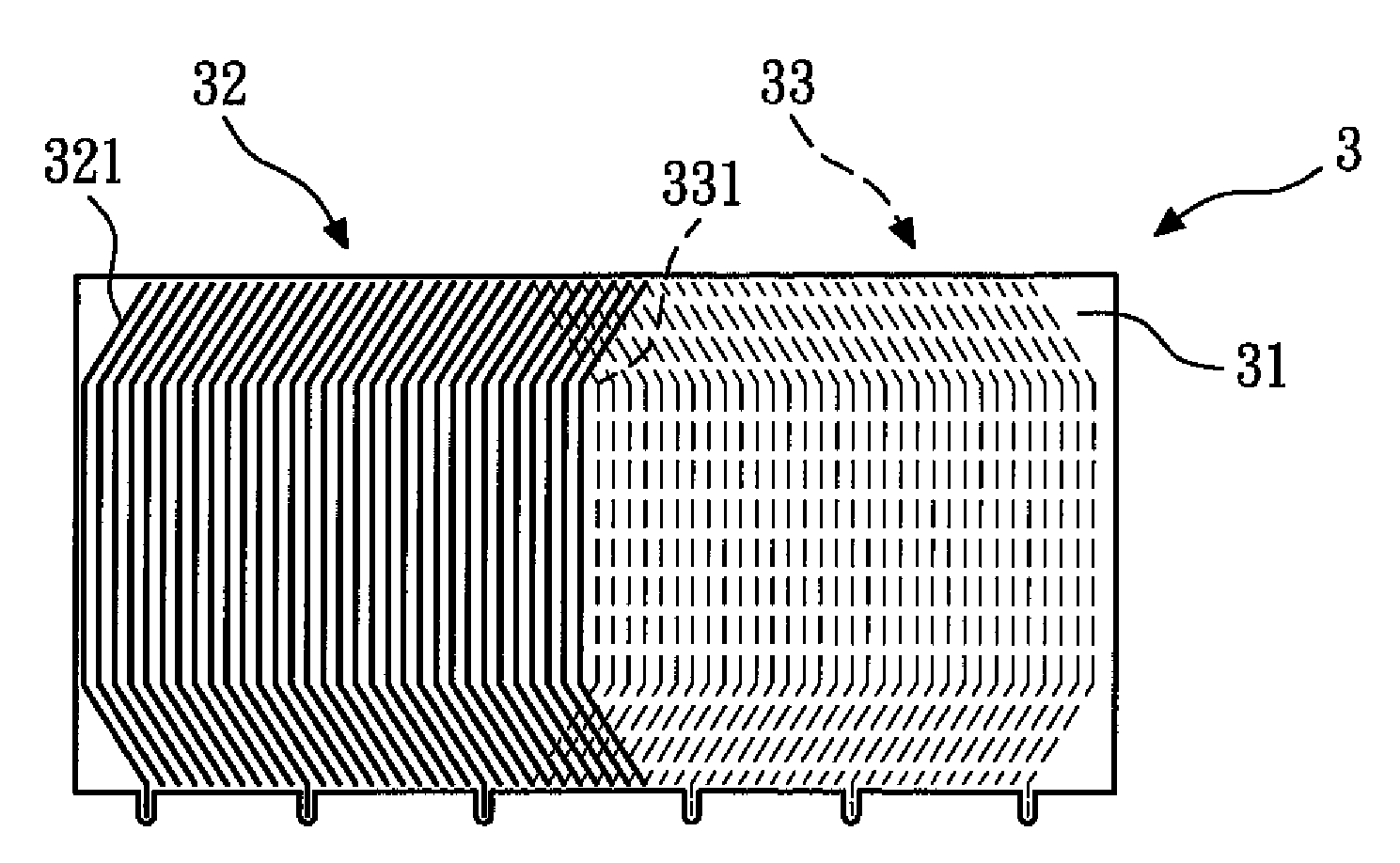
[0036]FIG. 4 shows a schematic top view of the flexible printed circuit board according to the present invention. The flexible printed circuit board 3 has a first surface 31, a second surface (not shown), and a circuit. The circuit has a first circuit 32 and a second circuit 33, the first circuit 32 is located on the first surface 31, and the second circuit 33 is located on the second surface and is shown by dashed circuit. The pattern of the first circuit 32 comprises a plurality of mutually parallel first wires 321, and the first wires 321 are quasi-U-shaped with openings in the horizontal direction (to the right in the drawing). The pattern of the second circuit 33 comprises a plurality of mutually parallel second wires 331, and the second wires 331 are quasi-U-shaped with openings in the horizontal direction (to the left in the drawing).

[0037]In this embodiment, the pattern of the first circuit 32 is the same as the pattern of the second circuit 33, that is, the pattern of the f...

third embodiment

[0038]FIGS. 5a and 5b show schematic top views of the flexible printed circuit board according to the present invention. FIG. 5a only shows a first circuit, and FIG. 5b only shows a second circuit. The flexible printed circuit board 4 has a first surface 41, a second surface (not shown), and a circuit. The circuit has a first circuit 42 and a second circuit 43, the first circuit 42 is located on the first surface 41, and the second circuit 43 is located on the second surface and is shown by dashed circuit. The pattern of the first circuit 42 comprises a plurality of wave-shaped first wires 421, and the first wires 421 are mutually parallel. The pattern of the second circuit 43 comprises a plurality of wave-shaped second wires 431, and the second wires 431 are mutually parallel.

[0039]In this embodiment, the pattern of the first circuit 42 is the same as the pattern of the second circuit 43, that is, the pattern of the first wires 421 is the same as the pattern of the second wires 431...


PUM

PropertyMeasurementUnit
flexibleaaaaaaaaaa
magnetic forceaaaaaaaaaa
densityaaaaaaaaaa

Abstract

The present invention relates to a slotless winding for a rotating electric machine and a manufacturing method thereof. The slotless winding includes at least one flexible printed circuit board having at least one circuit, and one piece of flexible printed circuit board(s) is curved or a plurality of pieces of flexible printed circuit board(s) is mutually combined to form a barrel shape, thereby simplifying the procedure of manufacturing the slotless winding, improving production speed and reliability, and enabling diversified designing schemes to meet the demands of the rotating electric machine. In addition, it is not necessary for the coil winding to be cured for assembling, and assembling yield is thus enhanced.

Description

BACKGROUND OF THE INVENTION[0001]1. Field of the Invention[0002]The present invention relates to a slotless winding for a rotating electric machine and a manufacturing method thereof. More particularly, the present invention relates to a slotless winding for a rotating electric machine and formed on a flexible printed circuit board and a manufacturing method thereof.[0003]2. Description of the Related Art[0004]FIGS. 1a-1d show schematic views of four kinds of conventional motors. In the four conventional motors, the same elements are labeled with the same reference numbers. In FIG. 1a, a first kind of conventional motor 1A includes a housing 11, a winding 12, a magnet 13, a shaft 14, and a gap 15. The winding 12 is fixed on the housing 11, the magnet 13 is fixed on the shaft 14, and the gap 15 exists between the winding 12 and the magnet 13. In electronic machinery, the winding and the components connected thereto are referred to as a primary, and the magnet and the components conne...

Claims


Application Information

Patent Timeline
Patent Type & Authority Applications(United States)
IPC IPC(8): H01F5/02H02K3/26H01F41/04H02K15/04
CPCH01F5/003H01F2017/006H02K3/26Y10T29/49162H05K1/165H05K2201/051Y10T29/49009H05K1/147H02K15/0407
Inventor YAN, GUO-JHIHHUANG, GUANG-MIAOWANG, HSIN-TEHSU, LIANG-YITSAI, MI-CHING
Owner METAL INDS RES & DEV CENT
Why Eureka
Try Eureka