Carbon nanotube for fuel cell, nanocomposite comprising the same, method for making the same, and fuel cell using the same

a fuel cell and carbon nanotube technology, applied in the direction of cell components, final product manufacturing, sustainable manufacturing/processing, etc., can solve the problems of carbon nanotube nucleating catalyst particles, and insufficient surface area and electrical conductivity of carbon backing substrates, so as to achieve high gas-reaction efficiency and improve efficiency

Inactive Publication Date: 2009-03-19
RGT UNIV OF CALIFORNIA
View PDF5 Cites 75 Cited by
  • Summary
  • Abstract
  • Description
  • Claims
  • Application Information

AI Technical Summary

Benefits of technology

[0025]The present invention provides carbon nanotubes for a fuel cell having an ultra-large surface area, a nanocomposite having high gas-reaction efficiency including the same, methods of fabricating the carbon nanotubes and the nanocomposite, and a fuel cell with improved efficiency including the nanocomposite.

Problems solved by technology

However, the dispersion of the catalyst in the backing substrate is not uniform, and the surface area and electrical conductivity of the carbon backing substrate are not large enough.
However, the use of fuel cell catalyst particles, such as Pt or Ru, and carbon nanotube nucleating catalyst particles is not clearly explained in the application.
Furthermore, the fabrication technique employed in the application is likely to result in a relatively low density of catalyst particles on the nanotube circumferential surface.

Method used


Image

  • Carbon nanotube for fuel cell, nanocomposite comprising the same, method for making the same, and fuel cell using the same
  • Carbon nanotube for fuel cell, nanocomposite comprising the same, method for making the same, and fuel cell using the same
  • Carbon nanotube for fuel cell, nanocomposite comprising the same, method for making the same, and fuel cell using the same

Examples


example 1

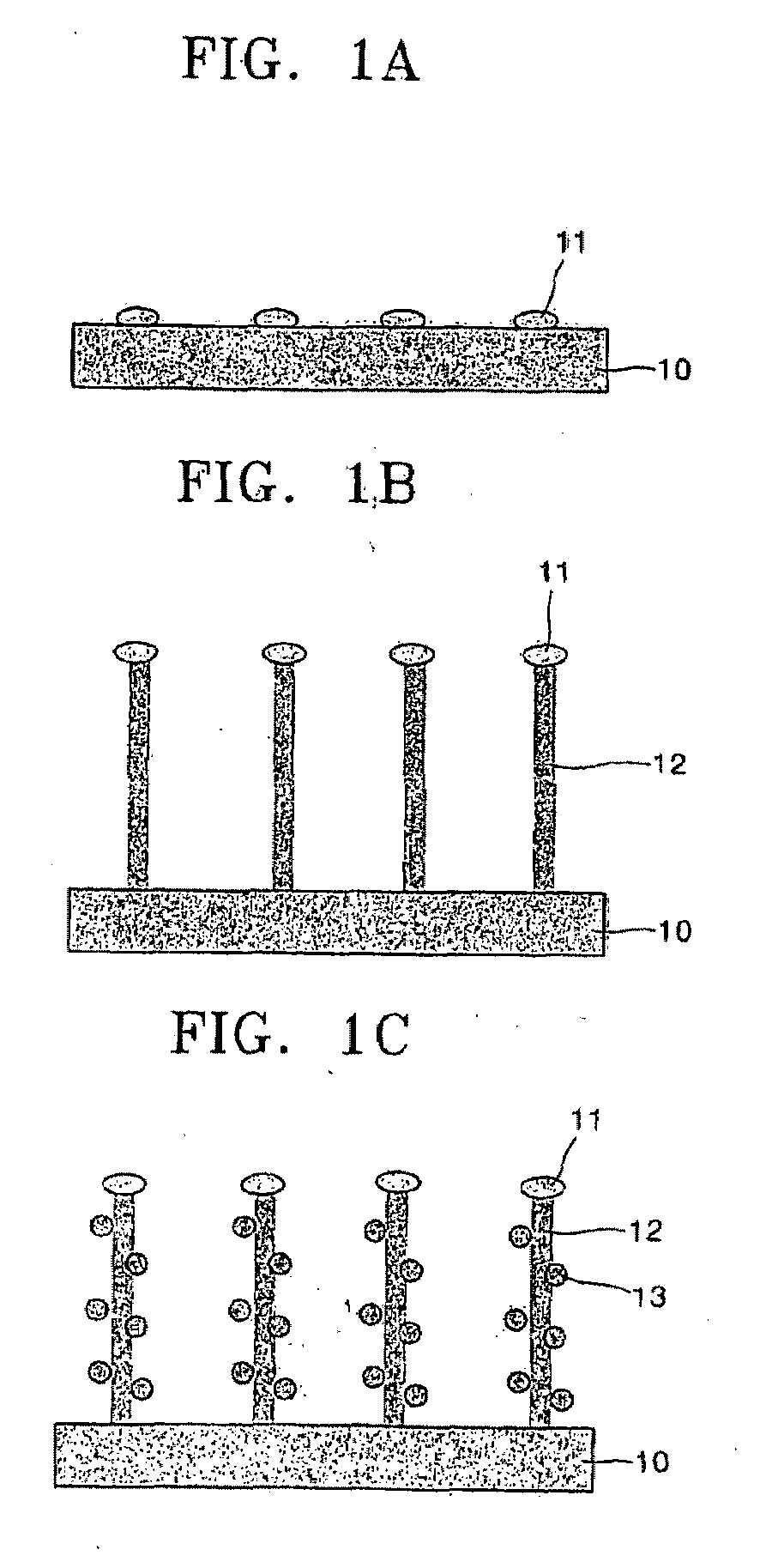
Fabrication of Aligned Primary Carbon Nanotubes

[0224]Ti was sputtered on carbon paper (total thickness: about 0.5 mm) to form an interface layer Ti with a thickness of about 7 nm, and then without exposure to air, a Ni layer of about 10 nm thickness was formed by sputtering. Then, a DC plasma CVD process was performed to grow carbon nanotubes at 700° C. for 20 min. During the CVD process, an electric field of about 450V was applied to align carbon nanotubes.

[0225]A mixed gas of ammonia (NH3) and acetylene (C2H2) was used in the CVD process, with a total NH3 and C2H2 pressure maintained at about 3 torr.

example 2

Electrodeposition of Ni Catalyst

[0226]Electrodeposition of Ni particles was performed using a mixed solution of a 45 g / L of NiCl2, 300 g / L of NiSO4 and 45 g / L of H3BO3 at 20° C. The deposition potential used was −1.2V vs saturated calomel electrode (SCE) produced from Aldrich and the loading was controlled by the total charge applied.

example 3

Supercritical Fluid Deposition of Ni Particles

[0227]A 10 mg of nickel precursor, nickel (II) 2,4-pentanedionate was loaded in the 10 mL capacity high pressure stainless steel reaction cell in which 1 cm2 of carbon paper having the carbon nanotube structure according to the present invention had been placed. Following the precursor loading, the valve V1, illustrated in FIG. 8, was closed while the valves V2, V3 and V4 illustrated in FIG. 8 were opened and hydrogen gas at a pressure of 3.0 atm was allowed to flow through the system for 5 min to expel the air inside.

[0228]After hydrogen loading, the valves V2 and V3 were closed to evacuate the reaction cell, and then the valve V4 was closed while V1 was opened to charge the 100 mL H2—CO2 mixing vessel with about 80 atm of CO2. After the H2 and the CO2 were mixed, the valve V3 was opened forcing the mixture into the reaction cell. The valves V1 and V3 were then closed to allow the dissolution of the Ni precursor in the CO2 solution. To ...


PUM

PropertyMeasurementUnit
diameteraaaaaaaaaa
diameteraaaaaaaaaa
angle of inclinationaaaaaaaaaa

Abstract

Provided are aligned carbon nanotubes for a fuel cell having a large surface area, a nanocomposite that includes the aligned carbon nanotubes loaded with highly dispersed nanoparticles of a metallic catalyst, methods of producing the carbon nanotubes and the nanocomposite, and a fuel cell including the nanocomposite. In the nanocomposite, nanoparticles of the metallic catalyst are uniformly distributed on external walls of the nanotubes. A fuel cell including the nanocomposite exhibits better performance.

Description

CROSS-REFERENCE TO RELATED PATENT APPLICATIONS[0001]This application claims the benefit of U.S. Patent Application No. 60 / 616,708, filed on Oct. 6, 2004, in the US Intellectual Property With respect to ice, the disclosure of which is incorporated herein in its entirety by reference.BACKGROUND OF THE INVENTION[0002]1. Field of the Invention[0003]The present invention relates to carbon nanotubes for a fuel cell, a nanocomposite including the same, methods of manufacturing the carbon nanotubes and the nanocomposite, and a fuel cell, and more particularly, to carbon nanotubes for a fuel cell to which highly-dispersed nanoparticles of a metallic catalyst are adhered, a nanocomposite including the same, and a fuel cell including the nanocomposite.[0004]2. Description of the Related Art[0005]Recently, with growing concerns about the environmental effects of fossil fuels and the eventual exhaustion of available energy resources, the design and fabrication of fuel cells have received a lot o...

Claims


Application Information

Patent Timeline
Patent Type & Authority Applications(United States)
IPC IPC(8): H01M4/00H05H1/24B32B37/00
CPCB82Y30/00H01M4/8605H01M4/8807H01M4/885H01M4/8853H01M4/8867Y02E60/50H01M4/8878H01M4/921H01M4/926H01M8/0234H01M8/1002H01M4/8871H01M8/1007Y02P70/50H01M4/92H01M4/96H01M8/02
Inventor PAK, CHAN-HOCHANG, HYUKJIN, SUNG-HOYE, XIANG-RONGCHEN, LI-HAN
Owner RGT UNIV OF CALIFORNIA
Why Eureka
Try Eureka