Therapeutic Catheter

a catheter and catheter tube technology, applied in the field of therapeutic catheters, can solve the problems of thrombosis from the internal vascular wall, obstruction of the downstream peripheral blood vessel, scattering of pultaceous plaque (atheroma) in the lesion, etc., and achieve the effect of rapid placement of the guide wire lumen, shortening the treatment period, and facilitating the passage of blood

Inactive Publication Date: 2009-03-19
KANEKA CORP
View PDF5 Cites 55 Cited by
  • Summary
  • Abstract
  • Description
  • Claims
  • Application Information

AI Technical Summary

Benefits of technology

[0023]The guide wire or the shaft of another catheter practically having a role of guide wire should be inserted from the opening at the distal or proximal end of the guide wire lumen for conventional therapeutic catheters. In the present invention, it is possible to shorten the treatment period by making the guide wire and the shaft of another catheter practically having a role of guide wire more easily, rapidly placed in the guide wire lumen. In particular in the method of treating blood vessel by using the shaft of a temporary occlusion balloon catheter as guide wire, it is possible to shorten the period needed for occluding blood vessel drastically, when compared with a treatment method of removing the atheroma generated by the balloon inflation described above with a suction catheter, because it is possible to eliminate operation for connecting/disconnecting the adapter for expansion or deflation of the temporary occlusion balloon by inserting the temporary-occlusion balloon catheter into an expa

Problems solved by technology

However, when obstruction of blood vessel is caused by thrombus formation, expansion of the obstructed site with a balloon catheter may result in liberation of the thrombus from the internal vascular wall and obstruction of the downstream peripheral blood vessel.
In addition in expanding the stricture site in blood vessel, if the lesion contains a great amount of pultaceous plaque, expansion of the balloon catheter may lead to scattering of the pultaceous plaque (atheroma) in the lesion and obstruction of the downstream peripheral blood vessel.
Commonly when the patient is in such a state, the surgeon waits until recovery of blood flow in coronary artery, which causes a problem of elongation of recovery period.
Even if recovery of blood flow is accelerated by administration of a vasodilator such as nitroglycerol or local administration of a thrombolytic agent such as urokinase depending on the circumstance, there remains the problem that the period until recovery of blood flow is longer.
Elongation of the cerebral ischemic state, which may result in death of cerebral cells and residual disorder, is very dangerous, and thus, sufficiently more caution should be given to prevent obstruction of peripheral blood vessel in angioplasty of cerebral or carotid artery than in angioplasty of other blood vessels.
The temporary occlusion balloon is inflated with an inflator connected to the catheter proximal end, but the inflator when connected prohibits operation of the other therapeutic catheter along the shaft of the temporary occlusion balloon catheter.
The period of temporary occlusion is preferably as short as possible, but it takes much labor and a longer period to open and close the sealing mechanism and to feed and withdraw the fluid for inflation.
Various adapters were studied for smoother operation of the sealing mechanism and for smoother inflation and deflation for improvement thereof, but the improvement is still insufficient.
It seems that a surgeon operates the expanding unit directly in such a case, but it is fairly difficult to operate a thin shaft directly with fingers.
In the case of threading, it is very difficult to insert a thin expanding unit into a thin shaft with a screw in actual clinical settings, causing a problem of less effective operation.
Alternatively in the case of friction, it is also difficult to

Method used


Image

  • Therapeutic Catheter
  • Therapeutic Catheter
  • Therapeutic Catheter

Examples


example 1

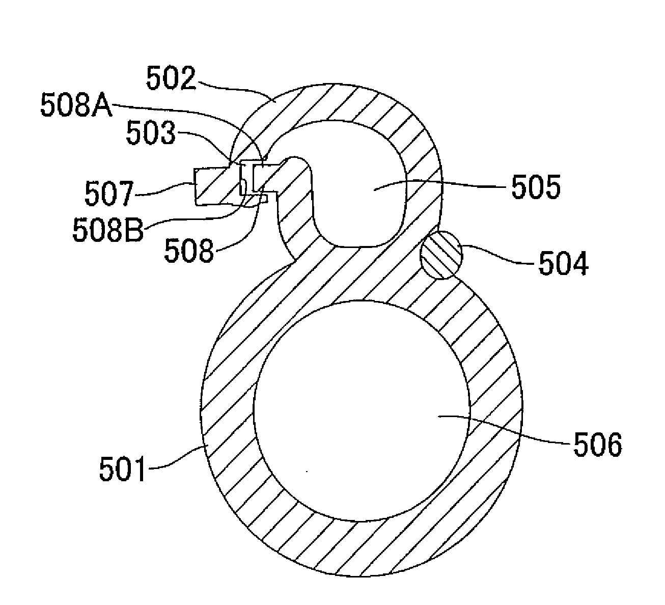
[0069]A main shaft consisting of a proximal shaft, a middle shaft and a distal shaft was prepared. A polyimide tube having an external diameter of 1.5 mm, an internal diameter of 1.3 mm, and a length of 1,100 mm was prepared by dipping in a polyamide acid varnish and used as the proximal shaft. A tube of a low-density polyethylene (LF480 M, Japan Polychem Corporation) having an external diameter of 1.5 mm, an internal diameter of 1.2 mm, and a length of 300 mm was prepared by extrusion molding and used as the middle shaft. Similarly, a tube of a low-density polyethylene (LF480 M, Japan Polychem Corporation) having an major diameter of approximately 1.9 mm, a minor diameter approximately 1.5 mm, and a length 10.5 mm and also having two lumens therein was prepared by extrusion molding and used as the distal shaft. A rod-shaped radiopaque marker having an elliptical cross section previously coated with low-density polyethylene (LF480 M, Japan Polychem Corporation) was placed at a posit...

example 2

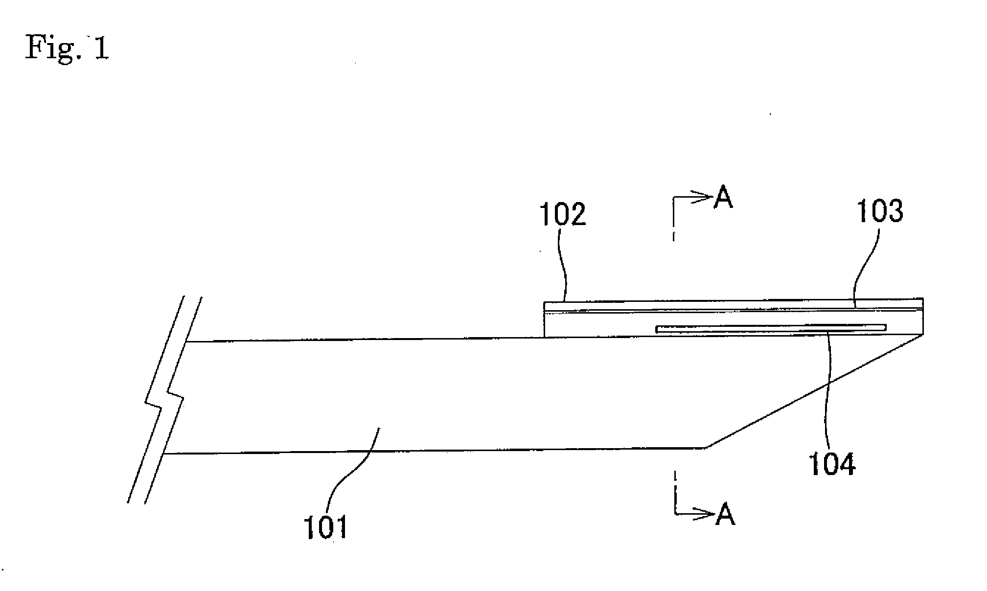
[0071]A main shaft consisting of a proximal shaft and a distal shaft was prepared. A polyimide tube having an external diameter of 1.5 mm, an internal diameter of 1.3 mm, and a length of 110 cm was prepared by dipping in a polyamide acid varnish and used as the proximal shaft. A tube of a polyamide elastomer (PEBAX 6333, ATOCHEM) having an external diameter of 1.5 mm, an internal diameter of 1.2 mm, and a length of 30 cm was prepared by extrusion molding and used as the distal shaft. The proximal shaft was narrowed at one end by heat drawing, and the narrowed region was inserted into the proximal region and bonded with a two-liquid-mixing urethane bonding agent, to give a main shaft. The most distal region of the main shaft was cut diagonally with a razor.

[0072]A tube having an external diameter of 0.68 mm, an internal diameter of 0.47 mm, and a length of 5.5 mm was prepared by using a polyamide elastomer having a Shore hardness of 72D (PEBAX 7233, ATOCHEM) by extrusion molding; a s...

example 3

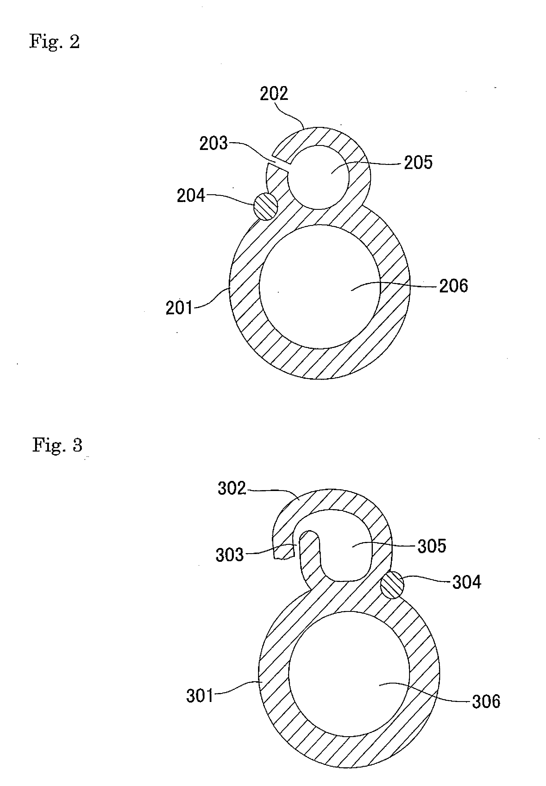
[0073]A main shaft consisting of a proximal shaft and a distal shaft was prepared. A polyimide tube having an external diameter of 1.5 mm, an internal diameter of 1.3 mm, and a length of 110 cm was prepared by dipping in a polyamide acid varnish and used as the proximal shaft. A polyamide elastomer (PEBAX 6333, ATOCHEM) tube having an external diameter of 1.5 mm, an internal diameter of 1.2 mm, and a length of 30 cm was prepared by extrusion molding and used as the distal shaft. The proximal shaft was narrowed at one end by heat drawing, and the narrowed region was inserted into the distal shaft and bonded with a two-liquid-mixing urethane bonding agent, to give a main shaft. The most distal region of the main shaft was cut diagonally with a razor.

[0074]A tube having an external diameter of 0.70 mm, an internal diameter of 0.47 mm, and a length of approximately 300 mm was prepared by extrusion molding of a polyamide elastomer having a Shore hardness of 63D (PEBAX 6333, ATOCHEM), and...


PUM


Abstract

The therapeutic catheter comprises a lumen communicating from the user's side end to the terminal tip part thereof, a main shaft having, at its tip, a guide wire lumen, a hub at its user's side end, and a slit in the guide wire lumen through its entire length, or the therapeutic catheter comprises a main shaft having a lumen communicating from the user's side end to the terminal tip part thereof, a guide wire shaft having, at its tip, a guide wire lumen, a hub at the user's side end of the main shaft, and a slit in the guide wire shaft through its entire length. The guide wire or the shaft of the other catheter playing the role of the guide wire can be rapidly disposed in the guide wire lumen through the slit.

Description

TECHNICAL FIELD[0001]The present invention relates to therapeutic catheters such as catheters for percutaneous introduction into the body for injection of a medicine and suction catheters for withdrawal of debris (foreign matter), such as thrombus generated in blood vessel and atheroma liberated into blood vessel, out of the body under negative pressure applied from the catheter proximal end.BACKGROUND ART[0002]When a body passage and vascular system such as blood vessel in the body is constricted or obstructed, traditionally percutaneous transluminal angioplasty (PTA, or PTCA: percutaneous transluminal coronary angioplasty) was practiced for expansion of the stricture or obstruction site of blood vessel and improvement of blood flow in the peripheral blood vessel. These treatment methods have been practiced frequently in many medical institutions and used commonly in operation of such cases. In addition, there are many reports recently on stents that are used for preservation of th...

Claims


Application Information

Patent Timeline
IPC IPC(8): A61M25/09A61M25/098
CPCA61M25/003A61M25/0043A61M25/0068A61M2025/1056A61M2025/0034A61M2025/0037A61M25/008
Inventor FUKAYA, KOHEI
Owner KANEKA CORP
Why Eureka
Try Eureka