Push Rod Engine With Inboard Exhaust

a technology of inboard exhaust and push rod engine, which is applied in the direction of machines/engines, fuel injecting pumps, mechanical equipment, etc., can solve the problems of increasing heat in the valley, requiring relatively long runners for conventional outboard exhaust manifolds, etc., and achieves less heat transfer, better heat conservation, and reduced exhaust-turbocharger connections.

Active Publication Date: 2009-03-26
FORD GLOBAL TECH LLC
View PDF38 Cites 29 Cited by
  • Summary
  • Abstract
  • Description
  • Claims
  • Application Information

AI Technical Summary

Benefits of technology

[0008]The present disclosure includes embodiments having various advantages. For example, embodiments of the present disclosure provide improved packaging by allowing the exhaust manifolds to be located in the valley with the turbocharger(s). This arrangement reduces the length of the exhaust-turbocharger connections resulting in better heat conservation and less heat transfer to outside peripherals such as the fuel pump, steering column, engine mounts, alternator, etc.

Problems solved by technology

However, conventional outboard exhaust manifolds require relatively long runners to route the exhaust to the turbocharger located in the valley.
In addition, the increased heat in th

Method used


Image

  • Push Rod Engine With Inboard Exhaust
  • Push Rod Engine With Inboard Exhaust
  • Push Rod Engine With Inboard Exhaust

Examples


Embodiment Construction

)

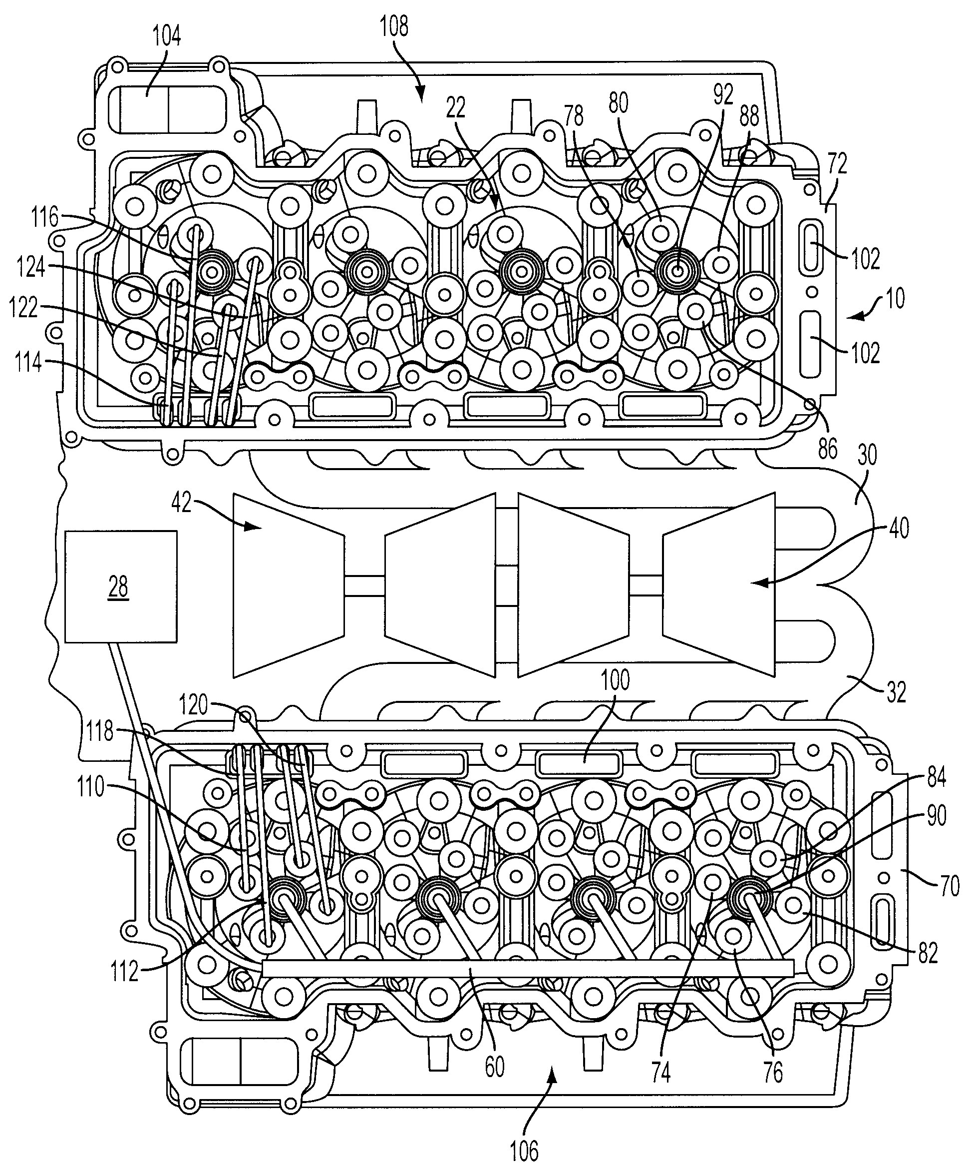
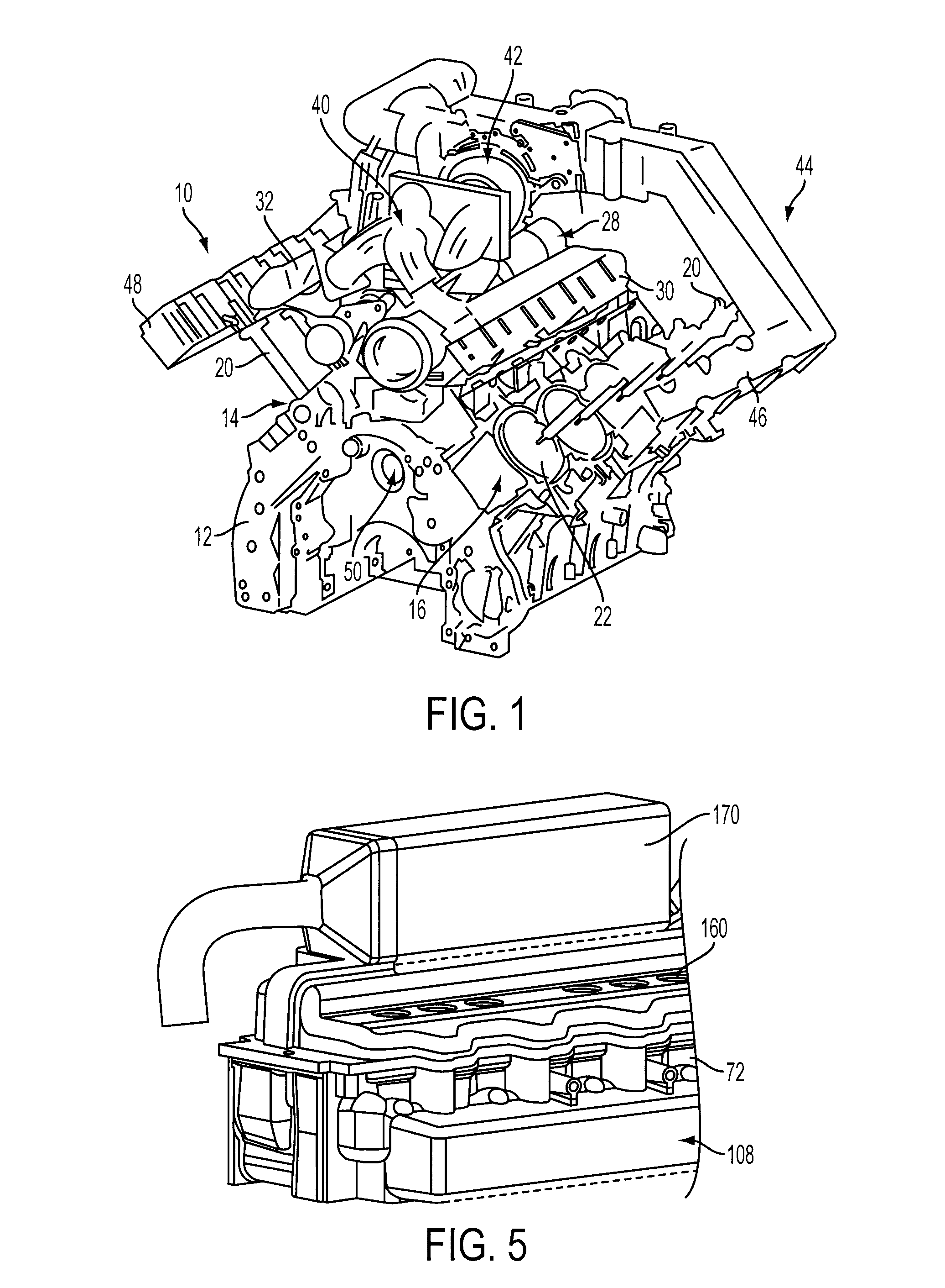
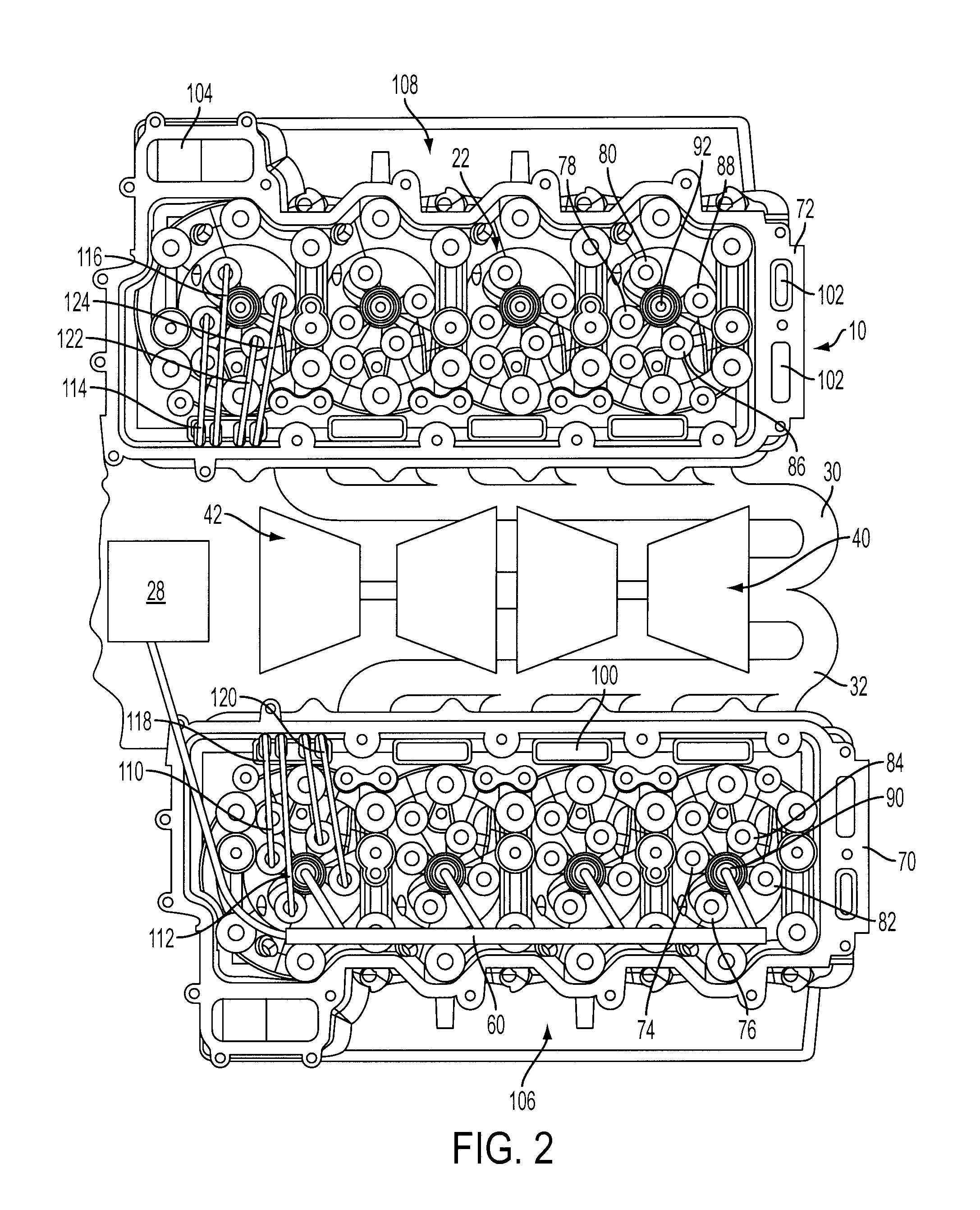
[0015]As those of ordinary skill in the art will understand, various features of the embodiments illustrated and described with reference to any one of the Figures may be combined with features illustrated in one or more other Figures to produce alternative embodiments that are not explicitly illustrated or described. The combinations of features illustrated provide representative embodiments for typical applications. However, various combinations and modifications of the features consistent with the teachings of the present disclosure may be desired for particular applications or implementations. The representative embodiments used in the illustrations relate generally to a turbocharged, four-stroke, multi-cylinder, direct-injected compression-ignition internal combustion engine. Those of ordinary skill in the art may recognize similar applications or implementations consistent with the present disclosure for other engine / vehicle technologies, including spark-ignition engines of v...


PUM


Abstract

A multiple cylinder internal combustion engine having an engine block with first and second cylinder banks arranged at an angle and longitudinally offset relative to one another and a camshaft disposed within the engine block for actuating valves associated with each cylinder includes first and second cylinder heads associated with the first and second cylinder banks and having an intake runner for each cylinder with an entrance disposed on an outward side, and an exhaust runner for each cylinder exiting the cylinder head on an inward side of the cylinder head generally rearward of an associated cylinder to facilitate positioning of one or more turbochargers and a fuel pump in the valley generally between the cylinder heads with the fuel pump disposed forward of the exhaust runner exits and associated exhaust manifolds while accommodating four valves per cylinder actuated by four pushrods extending through the cylinder heads forward of corresponding exhaust runner exits.

Description

BACKGROUND[0001]1. Technical Field[0002]The present disclosure relates to a system and method for providing inboard exhaust in a V-type, pushrod or cam-in-block internal combustion engine.[0003]2. Background Art[0004]Engine compartments of automotive vehicles have grown increasingly crowded as more components are added to the engine to improve performance and reduce emissions. V-type turbocharged engines may include a pushrod valvetrain having the camshaft located in the engine block, and the turbocharger(s) located in the valley formed between the two cylinder heads to provide a compact engine package. However, conventional outboard exhaust manifolds require relatively long runners to route the exhaust to the turbocharger located in the valley. This increases the package size and increases heat rejection associated with greater exposed surface area resulting in higher underhood temperatures and longer catalytic converter light-off times. It is desirable for packaging considerations...

Claims


Application Information

Patent Timeline
IPC IPC(8): F02B33/00
CPCF01L1/182F01L2001/256F01L2101/00F01L2103/00F01L2105/00Y02T10/144F01N2340/04F02B37/007F02B67/10F02M59/44F01N13/08F01L2301/00F01L2303/00F01L2305/00Y02T10/12
Inventor DIGGS, MATTHEW BYRNESCHRADER, MICHAEL JOSEPHMULLINS, JEFF ALLENFLUHARTY, JEFF D.
Owner FORD GLOBAL TECH LLC
Why Eureka
Try Eureka