Exhaust gas purification system and method for purifying exhaust gas

a technology of exhaust gas and purification system, which is applied in the direction of machines/engines, electrochemical generators, separation processes, etc., can solve the problems of reducing the energy efficiency of the system having the internal combustion engine, and combusting fuel and emitted exhaust gases, so as to achieve the effect of not reducing the energy efficiency or increasing the size of the system

Inactive Publication Date: 2009-04-02
TOYOTA JIDOSHA KK
View PDF3 Cites 12 Cited by
  • Summary
  • Abstract
  • Description
  • Claims
  • Application Information

AI Technical Summary

Benefits of technology

[0007]The present invention provides a system and a method for purifying exhaust gas, emitted from an internal combustion engine, that contains nitrogen oxides, without reducing the energy efficiency or increasing the size of the system.
[0009]In the first aspect of the present invention, the fuel cell uses the nitrogen oxides contained in the exhaust gas as an oxidant gas and uses hydrogen as the fuel gas to generate electricity by an electrochemical reaction between the hydrogen and the nitrogen oxides. In doing this, the anode reaction of the fuel cell may be expressed as H2→2H++2e−, and the cathode reaction may be expressed as (2 / X) NOx+2H++2e−→(1 / X) N2+H2O. The nitrogen oxides are decomposed by a reaction expressed as 2NOx+XH2→N2+XH2O. According to the first aspect, because the fuel cell operates in a prescribed temperature range that includes the temperature of the exhaust gas, it is possible to supply the exhaust gas to the cathode of the fuel cell without preheating the exhaust gas. It is, therefore, not necessary to provide the exhaust gas purifying system with a preheating device to preheat the exhaust gas, thereby increasing energy efficiency and enabling compactness of the system. That is, the first aspect of the present invention enables to provide the purification of exhaust gas, emitted from an internal combustion engine, that contains nitrogen oxides without reducing energy efficiency or increasing size of the system.
[0011]In the first aspect of the present invention, the fuel cell includes an electrolyte membrane in which a hydrogen-permeable metal layer that selectively allows hydrogen to permeate and an electrolyte layer having a proton-conductivity are laminated. That is, a hydrogen-separation membrane fuel cell is applied as the fuel cell. Because the operating temperature of the hydrogen-separation membrane fuel cell is approximately 400° C., which is approximately the same temperature as that of exhaust gas from a general internal combustion engine, the hydrogen-separation membrane fuel cell may be applied suitably to the present invention. Also, because the electrolyte membrane of the hydrogen-separation membrane fuel cell has a hydrogen-permeable metal layer with a relatively high strength, it is possible to make the electrolyte layer having the proton-conductivity thin, while maintaining the strength of the electrolyte membrane. Therefore, it is possible to make the membrane resistance of the electrolyte layer relatively low. As a result, by applying a hydrogen-separation membrane fuel cell to the present invention, it is possible to generate electricity while decomposing nitrogen oxides efficiently.
[0013]In the first aspect of the present invention, the cathode of the fuel cell has a platinum-based catalyst to promote the electrochemical reaction. Here, the term “platinum-based catalyst” includes, for example, platinum and alloys of platinum with ruthenium. By using a platinum-based catalyst as the cathode of the fuel cell, the fuel cell is capable of decomposing nitrogen oxides more efficiently as compared to a fuel cell using a cathode with other catalysts.

Problems solved by technology

Typically, such internal combustion engines combust fuel and emit exhaust gases.
It leads to a reduction in the energy efficiency of a system having the internal combustion engine, and an increase in the size of the system.

Method used


Image

  • Exhaust gas purification system and method for purifying exhaust gas
  • Exhaust gas purification system and method for purifying exhaust gas
  • Exhaust gas purification system and method for purifying exhaust gas

Examples


Embodiment Construction

[0019]In the following description and the accompanying drawings, the present invention will be described in the order of an exhaust gas purifying system, a fuel cell, and variations, in more detail in terms of example embodiments.

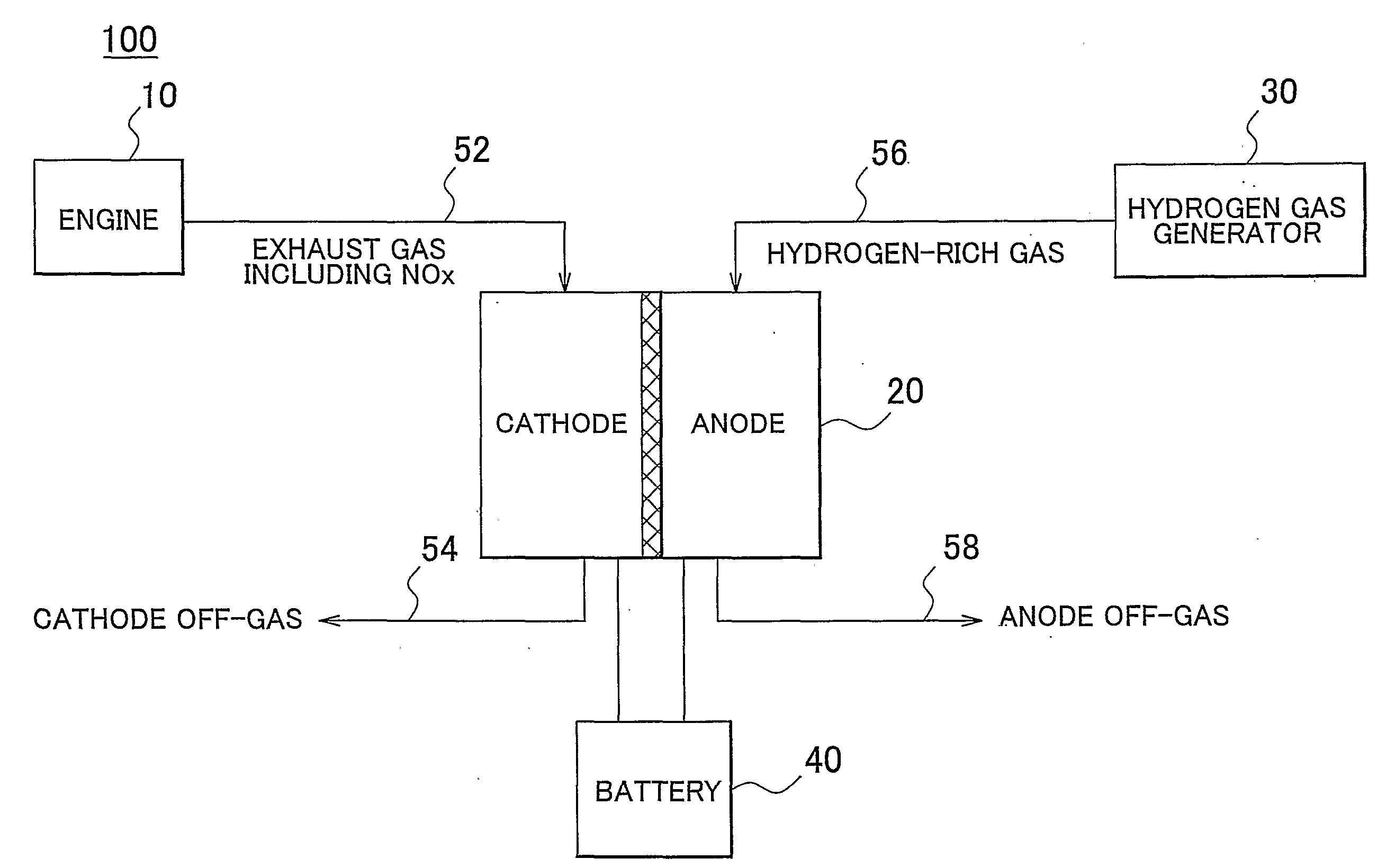
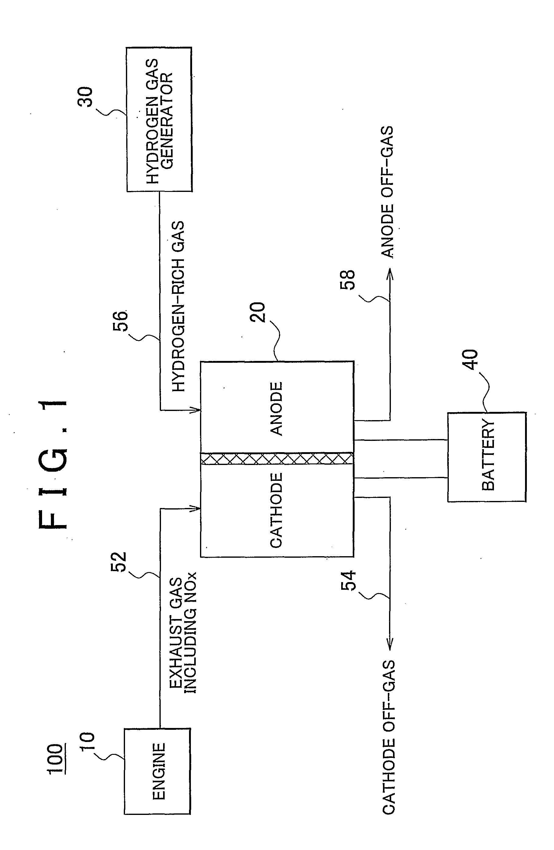
[0020]FIG. 1 is a diagram showing a schematic view of the exhaust gas purifying system 100 according to one example embodiment of the present invention. The exhaust gas purifying system 100 is installed in a vehicle that uses an internal combustion engine as a driving power source.

[0021]As shown in FIG. 1, the exhaust gas purifying system 100 has an engine 10, a fuel cell 20, a hydrogen gas generator 30, and a battery 40.

[0022]The engine 10 combusts gasoline supplied from a gasoline tank (not shown), and emits exhaust gas. The temperature of the exhaust gas is approximately 400° C. The exhaust gas contains nitrogen oxides (NOx). These nitrogen oxides, as described below, are decomposed electrochemically by the fuel cell 20.

[0023]The hydrogen gas generator ...


PUM


Abstract

An exhaust gas emitted from an engine (10) that contains nitrogen oxides is supplied to the cathode of a fuel cell (20), and a hydrogen-rich gas generated by the hydrogen gas generator (30) is supplied to the anode of the fuel cell (20). In the fuel cell (20), the nitrogen oxides are decomposed and electricity are generated by an electrochemical reaction between hydrogen and the nitrogen oxides. A hydrogen-separation membrane fuel cell, which operates at a temperature that is substantially the same temperature as that of the exhaust gas emitted from the engine (10) is used as the fuel cell (20).

Description

BACKGROUND OF THE INVENTION[0001]1. Field of the Invention[0002]The present invention relates to a system and a method for purifying exhaust gas, emitted from an internal combustion engine, that contains nitrogen oxides.[0003]2. Description of the Related Art[0004]Internal combustion engines are used as the driving power source for mobile conveyances such as vehicles. Typically, such internal combustion engines combust fuel and emit exhaust gases. These exhaust gases contain nitrogen oxides (NOx). Because nitrogen oxides pollute the atmosphere, they are usually removed by adsorption using an adsorbent or decomposed using a catalyst such as a NOx storage reduction catalyst or using plasma irradiation.[0005]Electrochemical processes have therefore been proposed to decompose nitrogen oxides. For example, Japanese Patent Application Publication No. 2001-70748 (hereinafter referred to as “JP-A-2001-70748”). describes process using a molten carbonate fuel cell to electrochemically decompo...

Claims


Application Information

Patent Timeline
Patent Type & Authority Applications(United States)
IPC IPC(8): F01N3/00
CPCB01D53/326B01D53/92C01B3/382C01B3/48C01B2203/0244Y02E60/50C01B2203/066C01B2203/1211F01N3/0892H01M8/0606H01M8/0681C01B2203/0283
Inventor KAWAI, HIROYUKI
Owner TOYOTA JIDOSHA KK
Why Eureka
Try Eureka