Semiconductor device reducing leakage current of transistor
a technology of semiconductor devices and leakage currents, applied in the direction of power consumption reduction, logic circuits, pulse techniques, etc., can solve the problems of disadvantageous increase in area of semiconductor devices, disadvantageous increase in power consumption due to leakage currents in operating states, etc., to reduce the leakage current of transistors in operating states.
- Summary
- Abstract
- Description
- Claims
- Application Information
AI Technical Summary
Benefits of technology
Problems solved by technology
Method used
Image
Examples
first embodiment
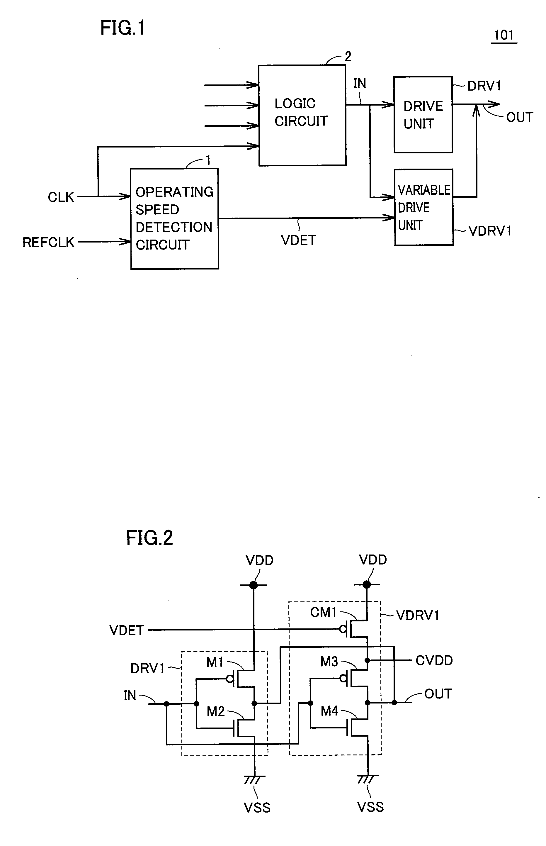
[0028]FIG. 1 shows a block diagram of a configuration of a semiconductor device according to a first embodiment of the present invention.
[0029]With reference to FIG. 1, semiconductor device 101 includes an operating speed detection circuit 1, a logic circuit 2, a drive unit DRV1 and a variable drive unit VDRV1.
[0030]Logic circuit 2 receives an external operating clock CLK, executes signal processing, based on operating clock CLK, and outputs a signal synchronized with operating clock CLK to each of drive unit DRV1 and variable drive unit VDRV1 via an input node IN.
[0031]Each of drive unit DRV1 and variable drive unit VDRV1 is a CMOS inverter, for example. That is, each of drive unit DRV1 and variable drive unit VDRV1 receives a signal from logic circuit 2 via input node IN, inverts a logic level of the received signal, and outputs the inverted signal to an output node OUT.
[0032]Operating speed detection circuit 1 detects a frequency of operating clock CLK. More specifically, operati...
second embodiment
[0064]A second embodiment relates to a semiconductor device in which variable drive units are increased in number, as compared with the semiconductor device according to the first embodiment. Details of the semiconductor device according to the second embodiment except details to be described later are similar to those of the semiconductor device according to the first embodiment.
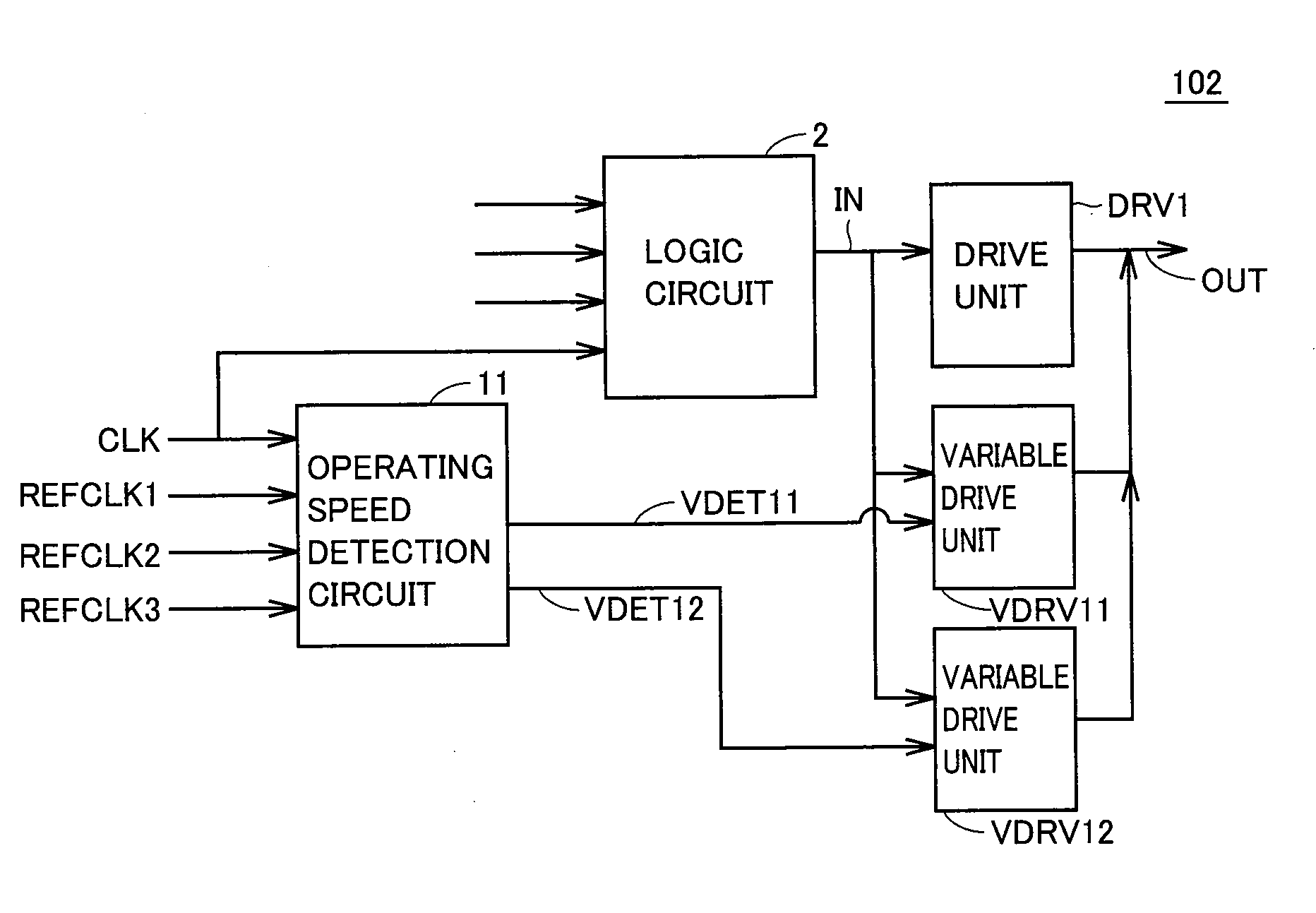
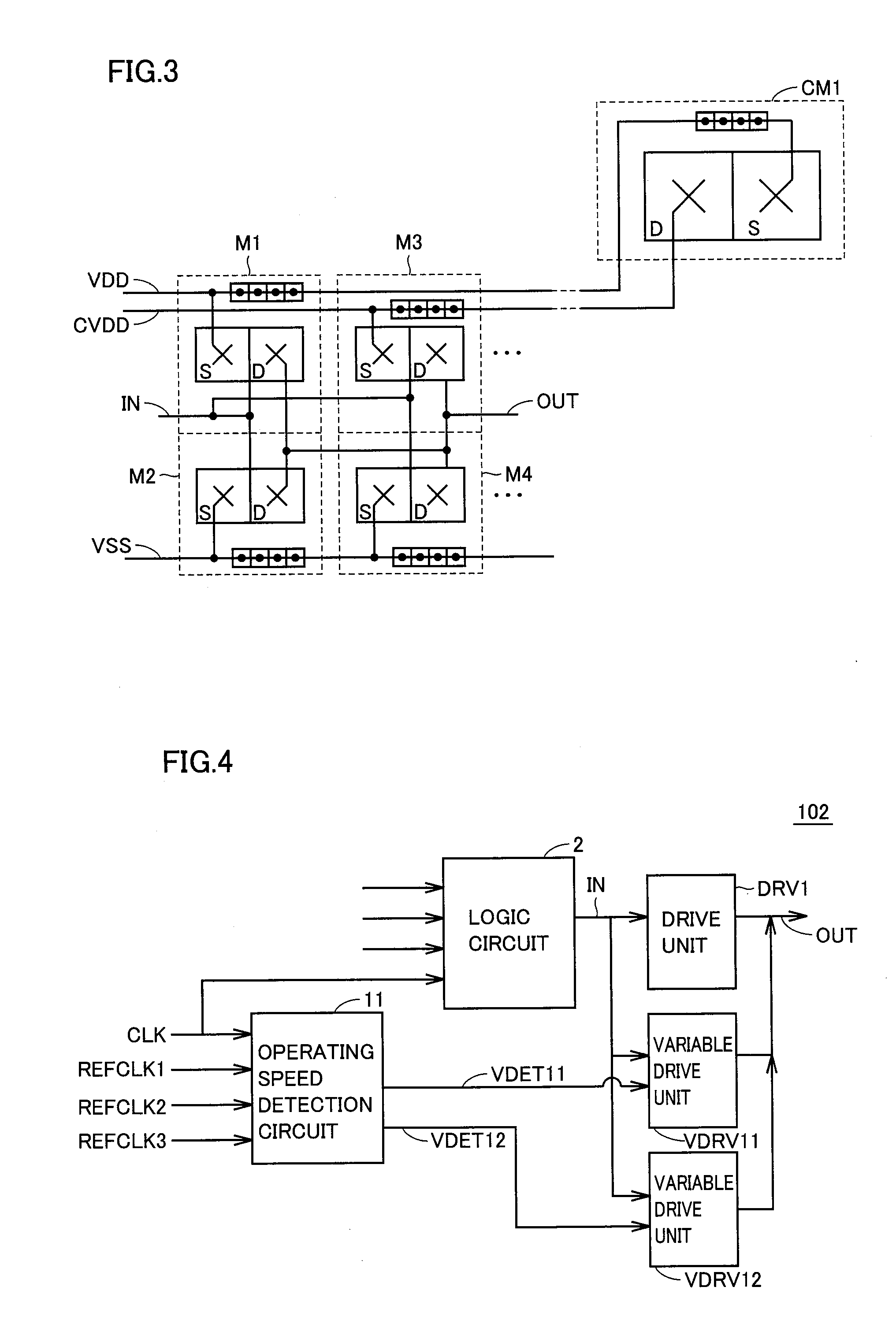
[0065]FIG. 4 shows a configuration of the semiconductor device according to the second embodiment of the present invention.
[0066]With reference to FIG. 4, semiconductor device 102 includes an operating speed detection circuit 11, a logic circuit 2, a drive unit DRV1, a variable drive unit VDRV11 and a variable drive unit VDRV12.
[0067]Each of drive unit DRV1, variable drive unit VDRV11 and variable drive unit VDRV12 is a CMOS inverter, for example. That is, each of drive unit DRV1, variable drive unit VDRV11 and variable drive unit VDRV12 receives a signal from logic circuit 2 via an input node IN, inverts a...
third embodiment
[0091]A third embodiment relates to a semiconductor device in which a configuration for changing a driving capability is changed, as compared with the semiconductor device according to the first embodiment. Details of the semiconductor device according to the third embodiment except details to be described later are similar to those of the semiconductor device according to the first embodiment.
[0092]FIG. 6 shows a configuration of the semiconductor device according to the third embodiment of the present invention.
[0093]With reference to FIG. 6, semiconductor device 103 includes an operating speed detection circuit 1, a back gate voltage control circuit 3, a logic circuit 2, a drive unit DRV21 and a variable drive unit VDRV21. Drive unit DRV21 includes a P-channel MOS transistor M11 and an N-channel MOS transistor M12. Variable drive unit VDRV21 includes a P-channel MOS transistor M13 and an N-channel MOS transistor M14.
[0094]Each of drive unit DRV21 and variable drive unit VDRV21 is...
PUM
 Abstract
Description
Claims
Application Information
 - R&D
- Intellectual Property
- Life Sciences
- Materials
- Tech Scout
- Unparalleled Data Quality
- Higher Quality Content
- 60% Fewer Hallucinations
Browse by: Latest US Patents, China's latest patents, Technical Efficacy Thesaurus, Application Domain, Technology Topic, Popular Technical Reports.
© 2025 PatSnap. All rights reserved.Legal|Privacy policy|Modern Slavery Act Transparency Statement|Sitemap|About US| Contact US: help@patsnap.com


