Line width roughness control with arc layer open

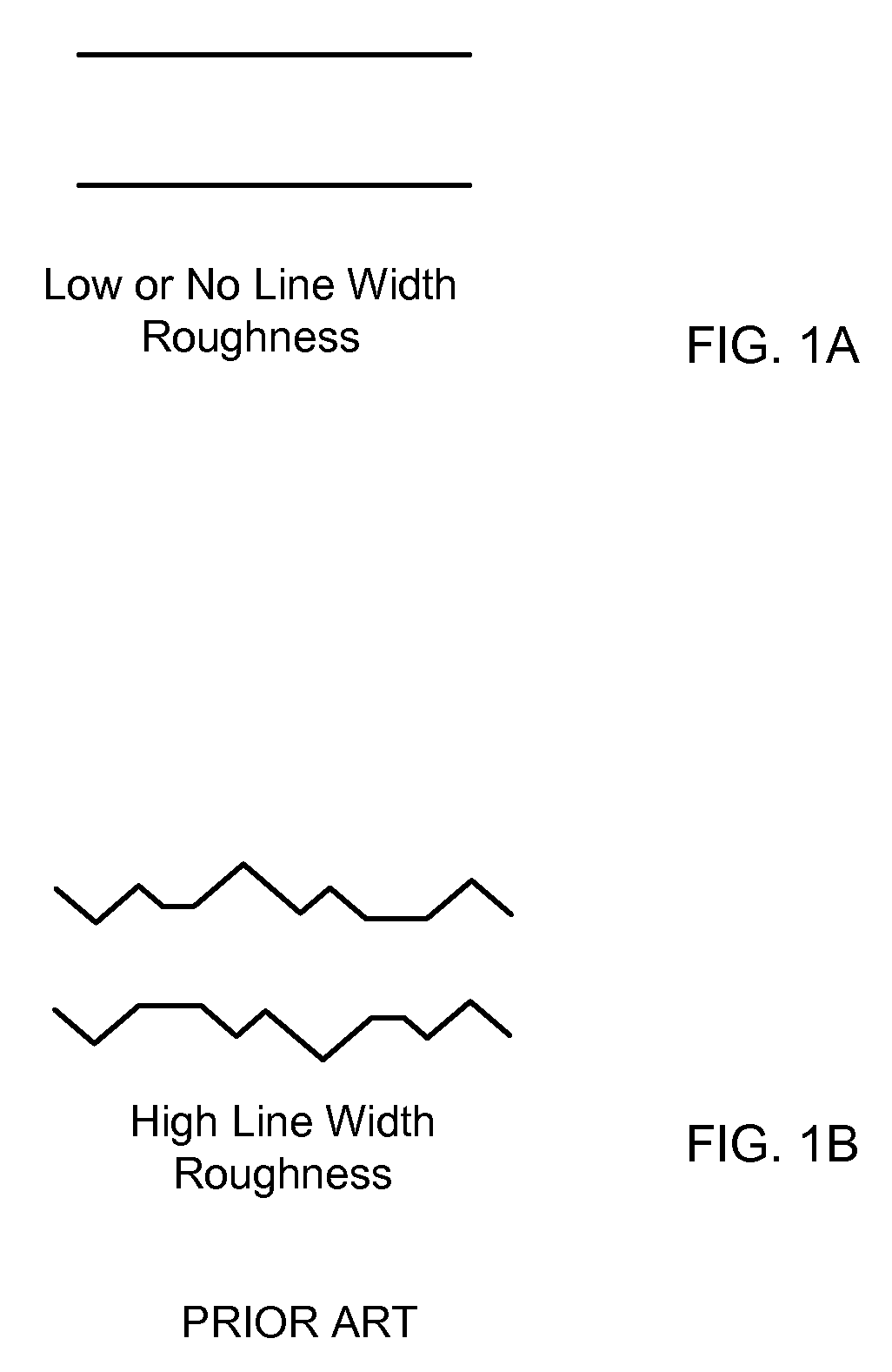
a technology of arc layer and line width, which is applied in the direction of basic electric elements, semiconductor/solid-state device manufacturing, electric devices, etc., can solve the problems of linear features patterned by photolithography, the rough edges of lines, and the “scalloping” of the photoresist sidewalls, so as to reduce the roughness of line width (lwr)

Active Publication Date: 2009-04-02
LAM RES CORP
View PDF13 Cites 16 Cited by
  • Summary
  • Abstract
  • Description
  • Claims
  • Application Information

AI Technical Summary

Benefits of technology

[0008]To achieve the foregoing and in accordance with the purpose of the present invention a method for etching an etch layer disposed below an antireflective coating (ARC) layer below a patterned mask is provided. The ARC layer is opened, and features are etched into the etch layer through the patterned mask. The opening the ARC layer includes (1) providing an ARC opening gas comprising a halogen containing gas, COS, and an oxygen containing gas, (2) forming a plasma from the ARC opening gas to open the ARC layer, and (3) stopping providing the ARC opening gas to stop plasma. The patterned mask may be a photoresist (PR) mask having a line-space pattern. COS in the ARC opening gas reduces line width roughness (LWR) of the patterned features of the etch layer.

Problems solved by technology

Such standing waves may result in defects such as sinusoidal “scalloping” of the photoresist sidewalls, or the formation of “feet” at the base of the photoresist layer.
As the design rules of ULSI reduced, the roughness of the edges of the lines (Line Width Roughness: LWR) of linear features patterned by photolithography becomes worse.
Jagged lines (i.e., with a high LWR) are generally very undesirable because the CD measured along the liner feature would vary from position to position, rendering operation of the resulting device unreliable.
Accordingly, the LWR problem worsens in the 193 nm lithography technology.

Method used


Image

  • Line width roughness control with arc layer open
  • Line width roughness control with arc layer open
  • Line width roughness control with arc layer open

Examples


Embodiment Construction

[0027]The present invention will now be described in detail with reference to a few preferred embodiments thereof as illustrated in the accompanying drawings. In the following description, numerous specific details are set forth in order to provide a thorough understanding of the present invention. It will be apparent, however, to one skilled in the art, that the present invention may be practiced without some or all of these specific details. In other instances, well known process steps and / or structures have not been described in detail in order to not unnecessarily obscure the present invention.

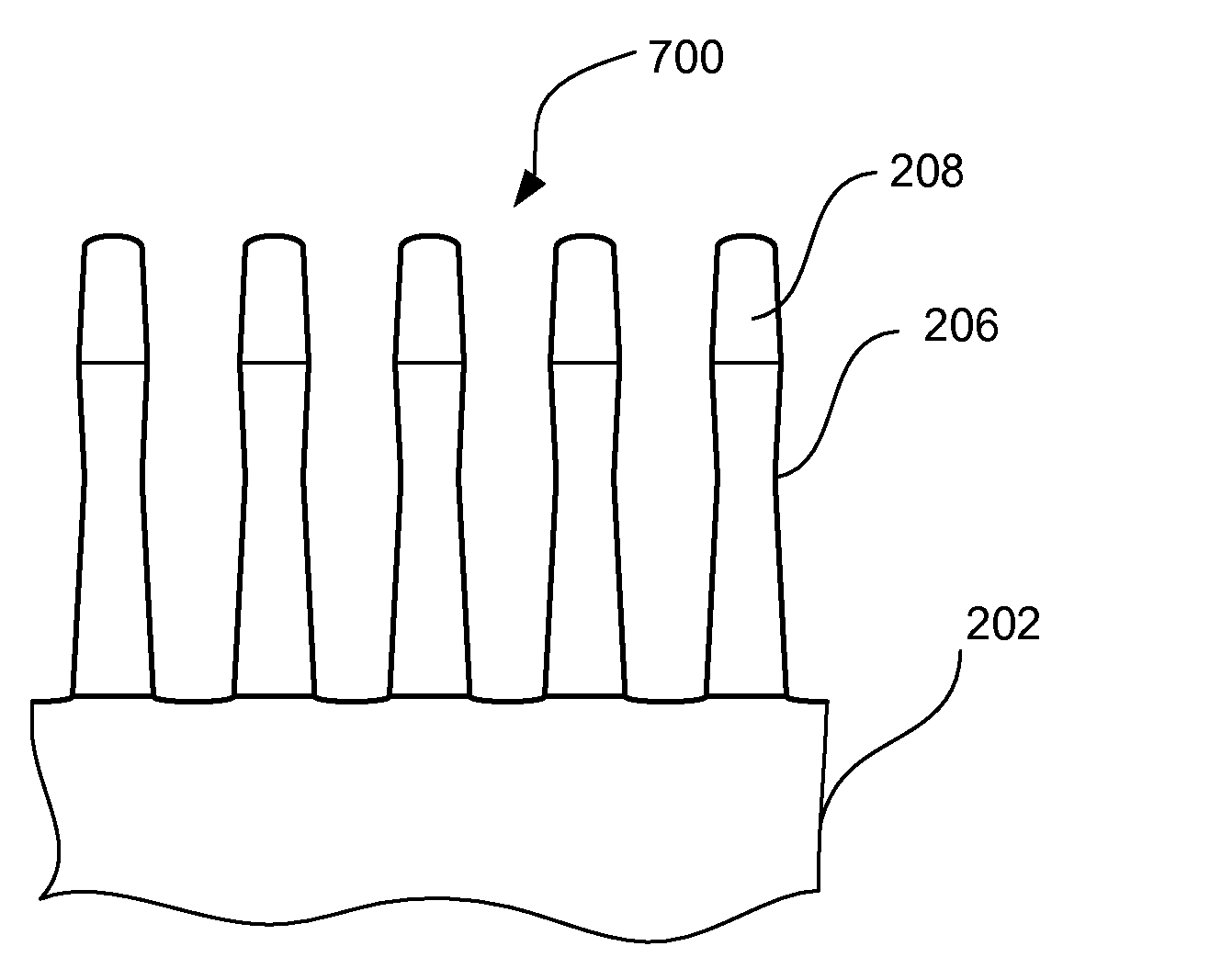
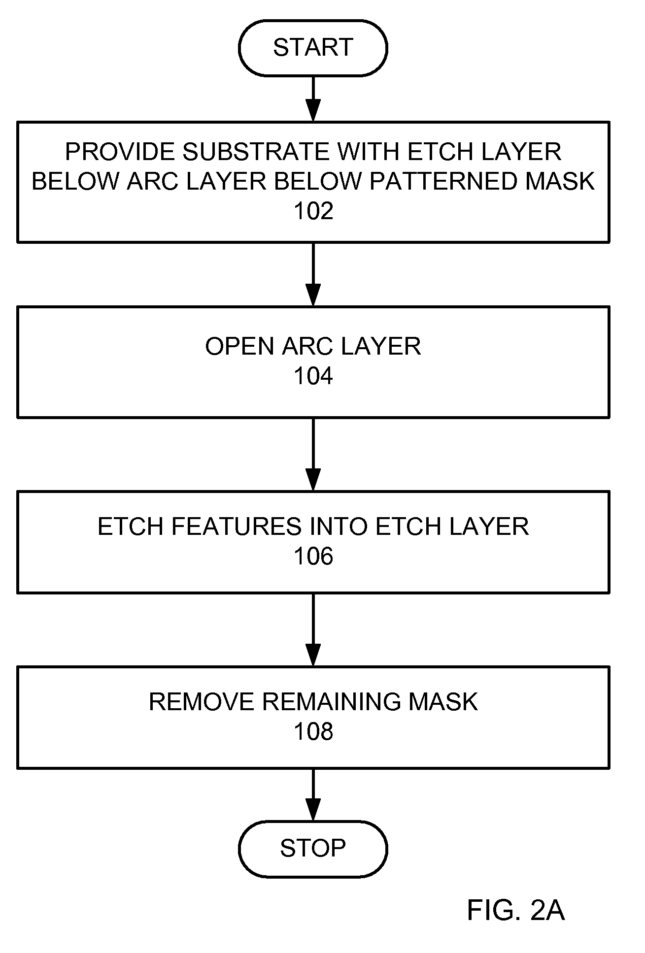
[0028]To facilitate understanding, FIG. 2A is a high level flow chart of a process used in an embodiment of the invention. A substrate with an etch layer disposed below an antireflective coating (ARC) layer below a patterned mask is provided (step 102). To facilitate understanding of the invention, FIG. 3 is a schematic cross-sectional view of a stack 200 of layers formed on a substrate 20...


PUM

PropertyMeasurementUnit
wavelengthaaaaaaaaaa
thicknessaaaaaaaaaa

Abstract

To achieve the foregoing and in accordance with the purpose of the present invention a method for etching an etch layer disposed below an antireflective coating (ARC) layer below a patterned mask is provided. The ARC layer is opened, and features are etched into the etch layer through the patterned mask. The opening the ARC layer includes (1) providing an ARC opening gas comprising a halogen containing gas, COS, and an oxygen containing gas, (2) forming a plasma from the ARC opening gas to open the ARC layer, and (3) stopping providing the ARC opening gas to stop the plasma. The patterned mask may be a photoresist (PR) mask having a line-space pattern. COS in the ARC opening gas reduces line width roughness (LWR) of the patterned features of the etch layer.

Description

CROSS REFERENCE TO RELATED APPLICATIONS[0001]This application claims priority under 35 U.S.C. §119(e) from co-pending U.S. Provisional Application No. 60 / 975,751, entitled “LINE WIDTH ROUGHNESS CONTROL WITH ARC LAYER OPEN”, filed Sep. 27, 2007, and naming Chi et al. as inventors, which is incorporated by reference in its entirety for all purposes.BACKGROUND OF THE INVENTION[0002]The present invention relates to etching an etch layer through a mask during the production of a semiconductor device. More specifically, the present invention relates to controlling the line width roughness (LWR) of fine features with opening of an antireflective coating layer through a mask during the production of semiconductor devices.[0003]During semiconductor wafer processing, features of the semiconductor device are defined in the wafer using well-known patterning and etching processes. In these processes (photolithography), a photoresist (PR) material is deposited on the wafer and then is exposed to ...

Claims


Application Information

Patent Timeline
Patent Type & Authority Applications(United States)
IPC IPC(8): H01L21/3065
CPCH01L21/31116H01L21/31144
Inventor CHI, KYEONG-KOOKIM, JONATHAN
Owner LAM RES CORP
Why Eureka
Try Eureka