

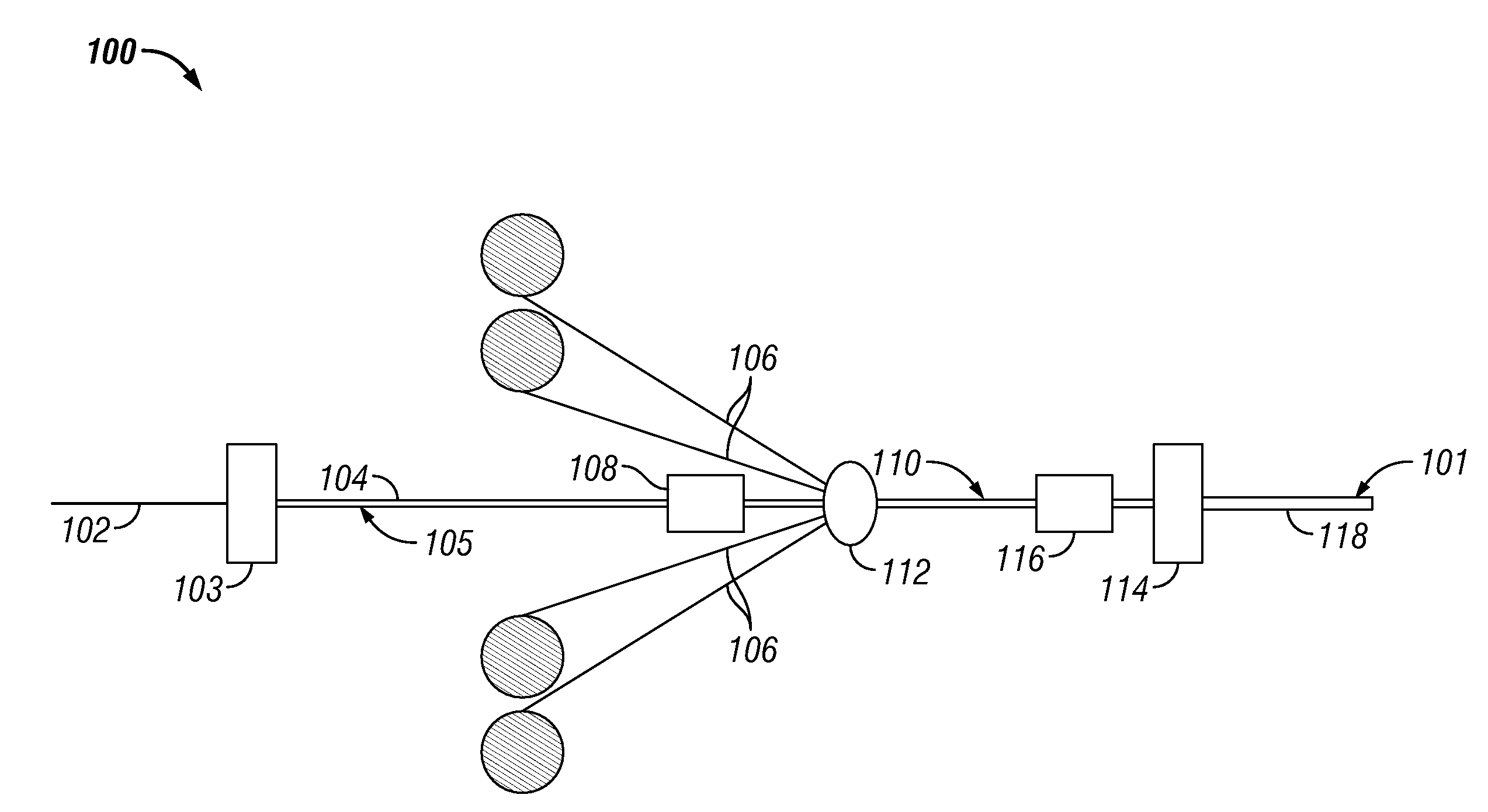
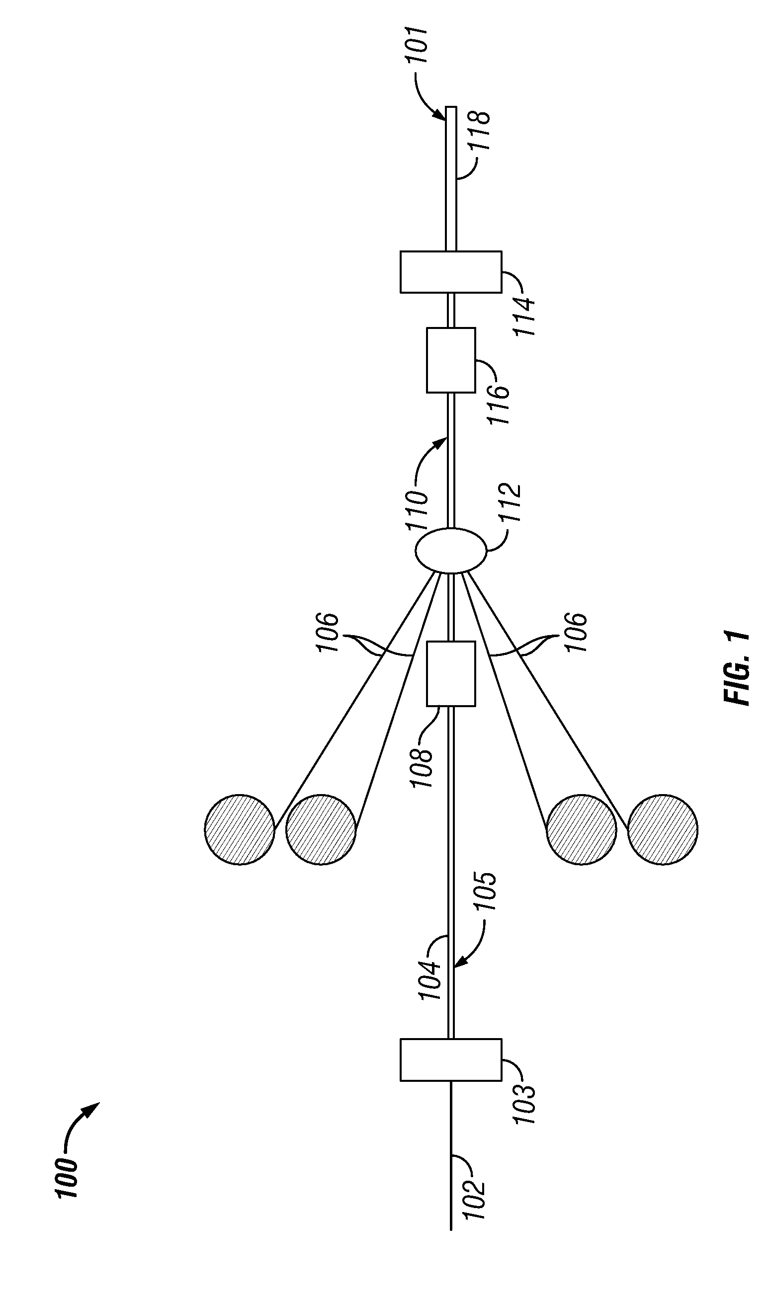
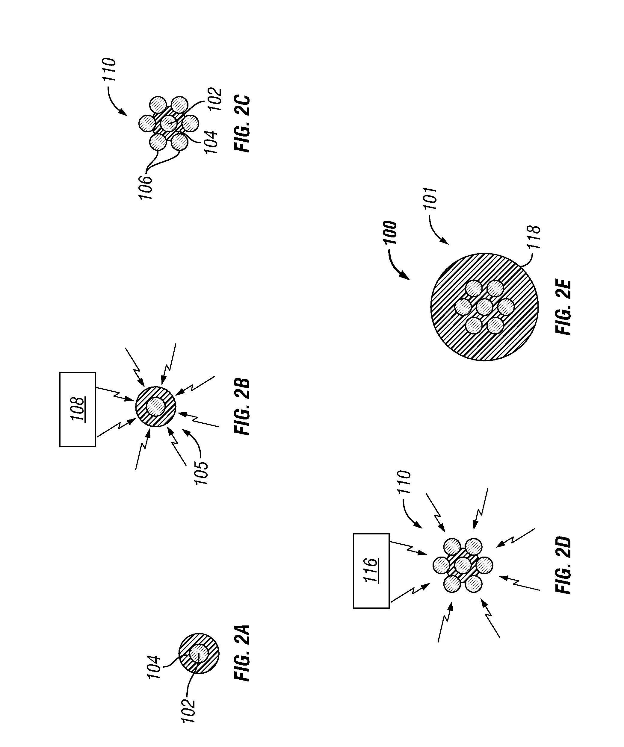
Methods of Manufacturing Electrical Cables
a manufacturing method and cable technology, applied in the direction of cables, insulated conductors, power cables, etc., can solve the problems of insulation not being able to penetrate into the spaces between the conductor strands, insulation to burst, insulation to bulge, etc., to achieve fast melting time, facilitate maximum bonding, and accelerate melting time
- Summary
- Abstract
- Description
- Claims
- Application Information
AI Technical Summary
Benefits of technology
Problems solved by technology
Method used
Image

Examples
Embodiment Construction
[0038]At the outset, it should be noted that in the development of any such actual embodiment, numerous implementation—specific decisions must be made to achieve the developer's specific goals, such as compliance with system related and business related constraints, which will vary from one implementation to another. Moreover, it will be appreciated that such a development effort might be complex and time consuming but would nevertheless be a routine undertaking for those of ordinary skill in the art having the benefit of this disclosure.
[0039]In the summary of the invention and this description, each numerical value should be read once as modified by the term “about” (unless already expressly so modified), and then read again as not so modified unless otherwise indicated in context. Also, in the summary of the invention and this detailed description, it should be understood that a concentration range listed or described as being useful, suitable, or the like, is intended that any a...
PUM
| Property | Measurement | Unit |
|---|---|---|
| diameter | aaaaa | aaaaa |
| diameter | aaaaa | aaaaa |
| strength | aaaaa | aaaaa |
Abstract
Description
Claims
Application Information