Piezoelectric/electrostrictive membrane type sensor

a membrane type sensor and piezoelectric technology, applied in the field of piezoelectric/electrostrictive membrane type sensors, can solve the problems of reducing the reliability of measured values, affecting the accuracy of measurement, and often using sensors in harsh places. , to achieve the effect of reducing the precision of measurement of the concentration of oxides and good sensitivity

Inactive Publication Date: 2009-04-16
NGK INSULATORS LTD
View PDF10 Cites 9 Cited by
  • Summary
  • Abstract
  • Description
  • Claims
  • Application Information

AI Technical Summary

Benefits of technology

[0031]Additionally, in the piezoelectric/electrostrictive membrane type sensor according to the present invention, when the oxide (e.g., sulfur oxide (SOX)), or the compound (e.g., sodium sulfate) of the oxide with the alkaline metal or the alkaline earth metal (e.g., sodium) is deposited on the surface of the piezoelectric/electrostrictive element, a problem might occur that the precision in the measurement of the concentration of the o

Problems solved by technology

Therefore, the sensor is not necessarily used in a place suitable for the sensor of an electric system, and the sensor is frequently used in a rather harsh place.
Moreover, even in a case where there is only little possibility of the gasification of the measurement target (the fluid), when the sensor is used in, for example, a factory, a surrounding environment is sometimes an atmosphere having high temperature, high humidity and high corrosive gas concentration, depending on the factory.
Even in this case, when the atmosphere extends around the sensor, the measurement precision of the piezoelectric/electrostrictive membrane type sensor m

Method used


Image

  • Piezoelectric/electrostrictive membrane type sensor
  • Piezoelectric/electrostrictive membrane type sensor
  • Piezoelectric/electrostrictive membrane type sensor

Examples


examples

[0078]The present invention will hereinafter be described in more detail with respect to examples, but the present invention is not limited to these examples.

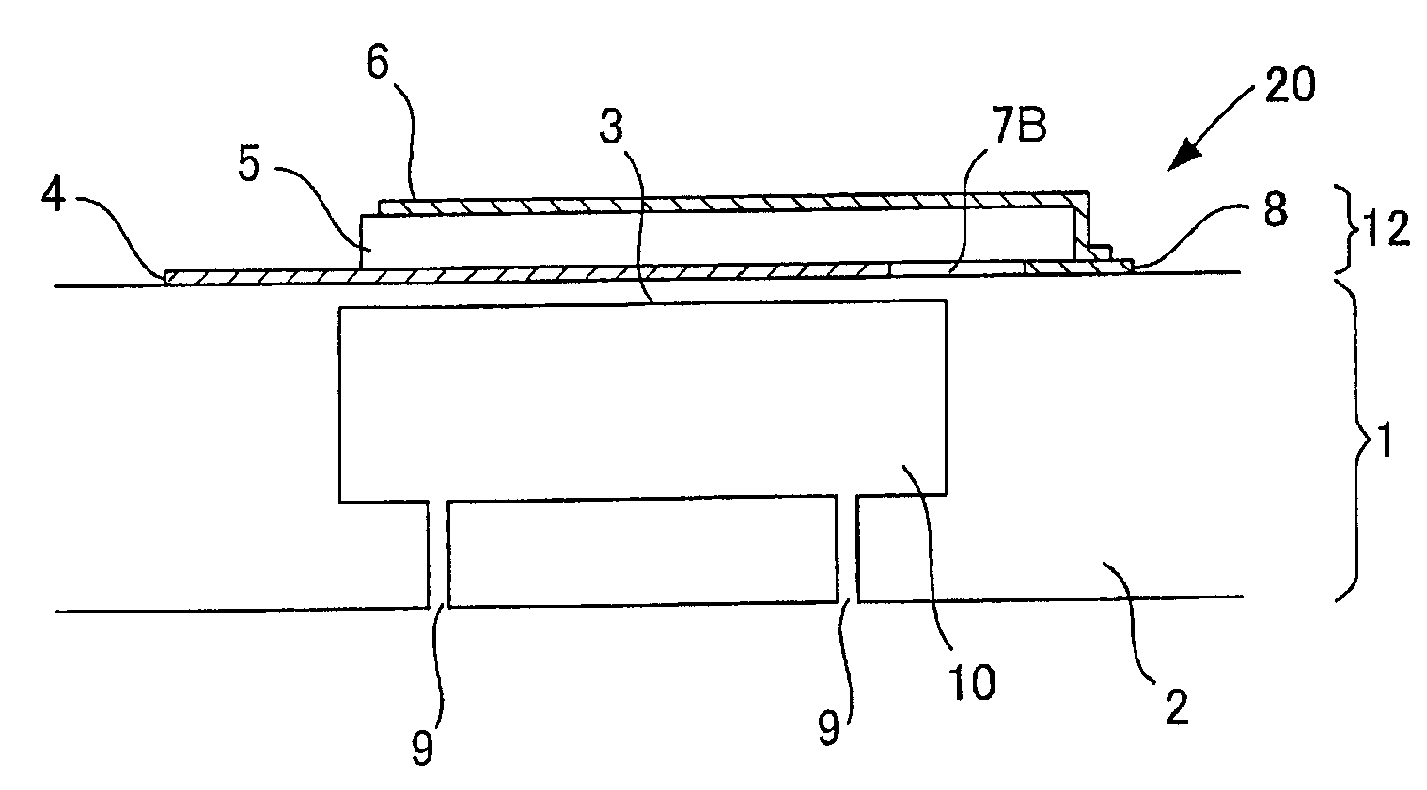
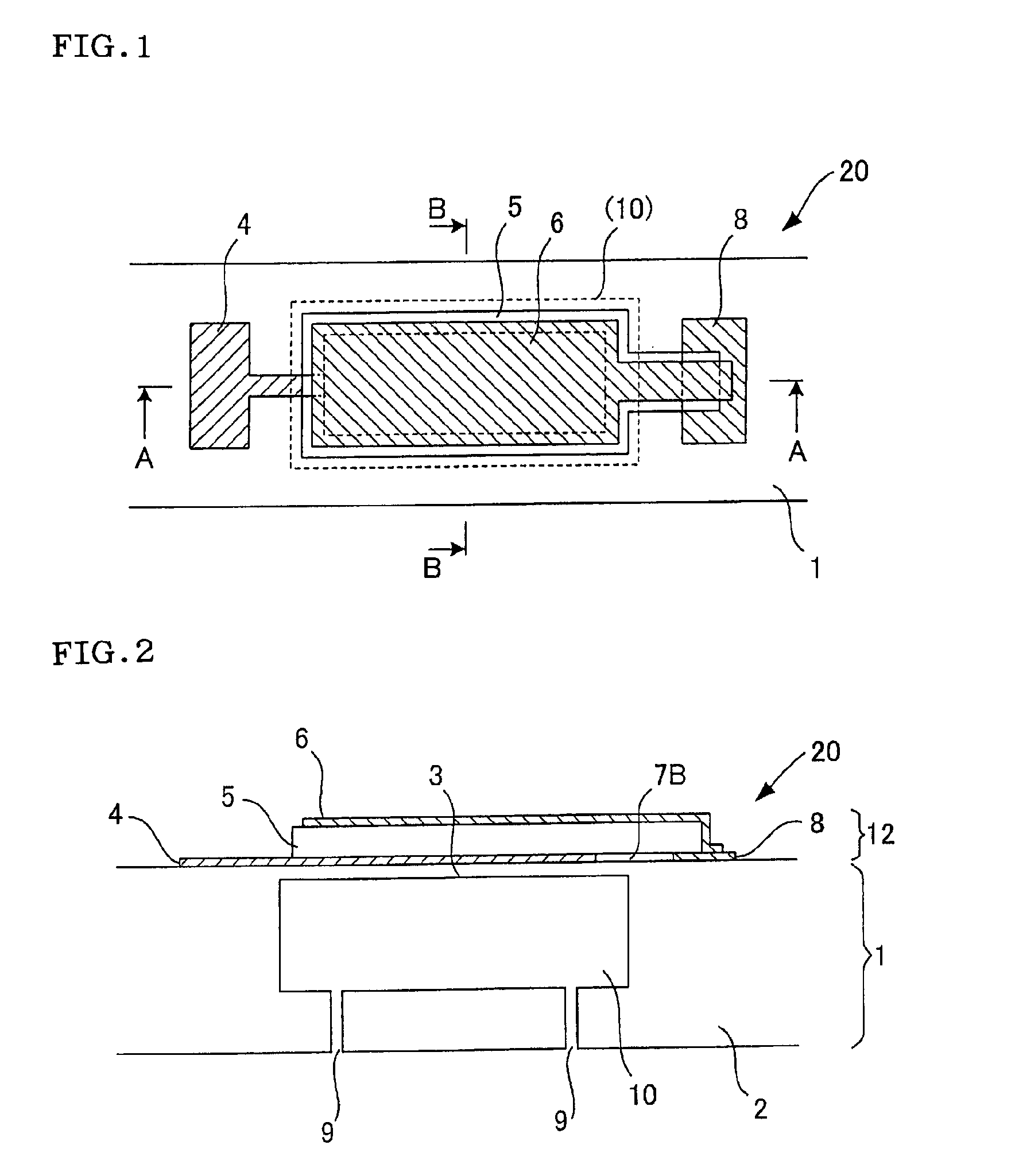
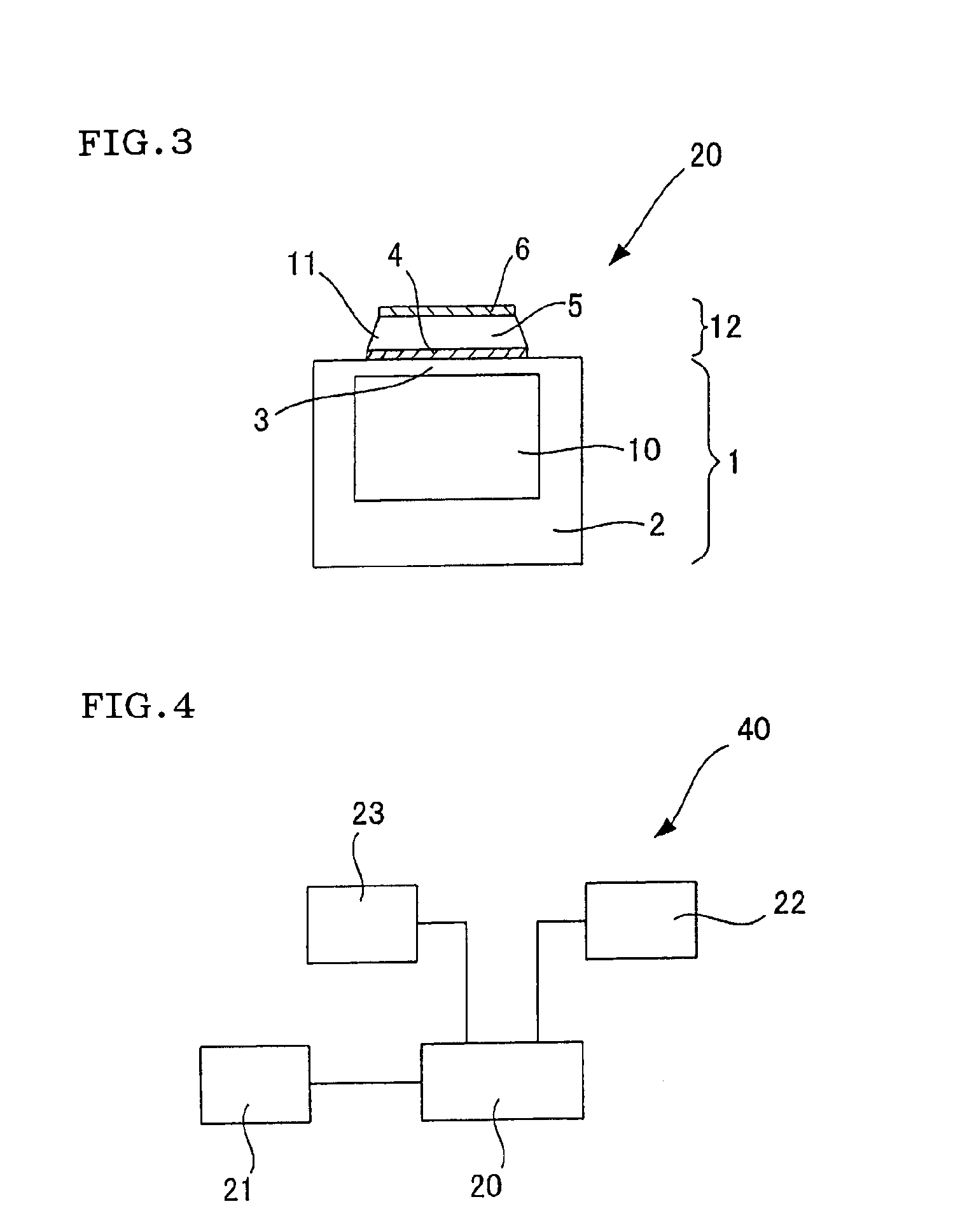
[0079]Six piezoelectric / electrostrictive membrane type sensors having the same configuration (without any bonding layer) as that of the above piezoelectric / electrostrictive membrane type sensor 20 were prepared. First, the powder of stabilized zirconium oxide, a binder and a dispersant were mixed to prepare a slurry, this slurry was subjected to a defoaming treatment, and the resultant material was formed by a doctor blade process to obtain a plurality of ceramic green sheets. Then, hole portions were made in the ceramic green sheets, if necessary. The ceramic green sheet constituting a thin diaphragm portion later, the ceramic green sheet in which the hole portion constituting a cavity was made, and the ceramic green sheet in which the hole portions constituting through holes were made were laminated in this order, and pressed...


PUM

PropertyMeasurementUnit
Thicknessaaaaaaaaaa
Electrical resistanceaaaaaaaaaa
Electric propertiesaaaaaaaaaa

Abstract

Disclosed is a piezoelectric/electrostrictive membrane type sensor 20 provided with a ceramic base body 1 and a piezoelectric/electrostrictive element 12. The ceramic base body is provided with a thin diaphragm portion 3, a thick portion 2 and a cavity 10 formed by the portions. The piezoelectric/electrostrictive element is arranged on the ceramic base body 1 and includes a piezoelectric/electrostrictive body 5, and an upper electrode 6 and a lower electrode 4 sandwiching the piezoelectric/electrostrictive body 5. In the piezoelectric/electrostrictive membrane type sensor 20, the piezoelectric/electrostrictive body 5 contains an alkaline metal or an alkaline earth metal, and the upper electrode 6 and the lower electrode 4 contain gold or platinum. When there is a change in the atmosphere at a place where the sensor is used, the sensor copes with such change and at least prevents continuation of low-quality measurement.

Description

TECHNICAL FIELD[0001]The present invention relates to a piezoelectric / electrostrictive membrane type sensor capable of confirming the measurement reliability of the sensor itself.BACKGROUND ART[0002]A piezoelectric / electrostrictive membrane type sensor can be used for measuring fluid characteristics such as viscosity, density and concentration by use of the electromechanical converting function of a piezoelectric / electrostrictive element in which a membrane-like piezoelectric / electrostrictive body disposed in the sensor is sandwiched between a pair of electrodes. For example, when the piezoelectric / electrostrictive membrane type sensor (the piezoelectric / electrostrictive element) is vibrated in a fluid, a mechanical resistance is received by the viscosity resistance of the fluid, and the electric constant of the piezoelectric / electrostrictive element changes in a constant relation with respect to the mechanical resistance. Therefore, the sensor can detect the constant to measure the...

Claims


Application Information

Patent Timeline
IPC IPC(8): G01N9/00H01L41/04H01L41/22H01L41/312H01L41/39
CPCG01N11/16G01N29/022G01N29/2462G01N33/0042G01N33/2835G01N2291/014Y10T29/42G01N2291/02818H01L41/0973H01L41/0477H01L41/1873H01L41/1878H01L41/312G01N2291/02809H10N30/877H10N30/2047H10N30/853H10N30/045H10N30/074
Inventor SHIMIZU, HIDEKIOHNISHI, TAKAOYAMADA, TOMOHIRO
Owner NGK INSULATORS LTD
Why Eureka
Try Eureka