
Test device for determining an analyte concentration

a test device and analyte technology, applied in the field of test devices, can solve the problems of increasing the space occupied by the measuring system, increasing the material cost of the measuring system, and fewer test strips being able to be accommodated in the corresponding container, so as to achieve simple decoupling of gears and increase the discreetness of the devi

Active Publication Date: 2009-04-16
ROCHE DIABETES CARE INC
View PDF6 Cites 26 Cited by
  • Summary
  • Abstract
  • Description
  • Claims
  • Application Information

AI Technical Summary

Benefits of technology

[0027]In yet other embodiments, the test device can be made shallow and can thus be carried inconspicuously. Furthermore, a disruptive motor noise or gear noise can be avoided, since it is possible to provided the test device without an electric motor. The system costs of the test device can be comparatively low, since costly component parts, e.g. motors, large batteries, etc., can be dispensed with. The material costs too, in particular for disposable material, can be comparatively low, since smaller test elements can be used.
[0028]To prepare for determination of an analyte concentration, for example a blood glucose concentration measurement, certain embodiments of the test device are simply opened, for example folded open. Tensioning of a transport device or actuation of an electric motor via a corresponding button is thus not necessary. This also ensures that patients with a limited range of movement, in particular elderly patients or children, can also safely handle the test device.
[0031]According to the embodiments of the present invention, the test device can also be configured in such a way that, when the housing is closed, the at least one test element is conveyed from the measurement position back into the storage position. Typically, this conveying can also be effected by the dispensing device, which can have suitable means to permit this conveying. For example, this conveying can again involve a rotational movement of the at least one lest element. This aspect of the invention ensures that used test elements do not have to be removed, but instead are transferred back into the storage device, where they can be stored hygienically. Thus, separate disposal of each individual test element is not required. This also increases the discreetness with which the device can be used.
[0032]In yet other embodiments, the present invention further comprises a decoupling mechanism which, when so desired by the user, prevents the dispensing device from opening the test device. This can be achieved, for example, by simple decoupling of gears (e.g. decoupling of a toothed wheel connected to the housing from a toothed wheel connected to the dispensing device), in a way that is known to a person skilled in the art. Thus, for example, the housing can be opened without a test element being dispensed, if the user wishes this to be so and acts accordingly (for example by pressing a decoupling button). In this way, for example, a user can open the housing in order, for example, to read off electronic measurement results from a memory of the test device, without a test element being used. Alternatively, the housing can also be designed such that it can be opened only with a test element being dispensed.
[0036]In connection with the test device according to the invention, embodiments of a test element are proposed according to the invention which can cooperate with the dispensing device of the test device. In one such embodiment, the test element has at least one connecting device for connecting the test element to the dispensing device. For example, this connecting device can be a hook that engages in a corresponding cutout in the dispensing device. In another example, the test element has an opening for the passage of an axle of the dispensing device. This opening can, for example, be a round or polygonal opening in the inner area of the test element, or said opening can also be an opening arranged at the edge of the test element, for example a cutout on the edge of the test element. In this way, the test element can be rotated by means of the axle, in order to transfer it from the storage position to the measurement position.
[0038]Embodiments of the test device and the test element according to the present invention can be used by a patient according to the following exemplary sequence of steps: The patient carries the test device, in the closed state, in a corresponding transport container or in a pocket. To carry out a measurement, for example a blood glucose concentration measurement, the patient removes the test device from the pocket and opens the housing of the test device. Opening it can involve the device simply being, folded open, for example, or additional actuation of an operating element may be necessary to open it. For example, the test device can have an opening button, which has to be actuated in order to open the test device. Inadvertent opening of the test device can be avoided in this way.

Problems solved by technology

However, the measuring systems known from the prior art, in which a blood glucose concentration is determined by means of a single test strip (single strip systems) and in which an individual test strip for a measurement has to be inserted into the device, have numerous disadvantages in practice.
An increased size of the test strips, however, has the effect that the space taken up by the measuring systems increases and fewer test strips can be accommodated in a corresponding container.
This increased space requirement also increases the material costs of the measuring systems.
The manual handling of the test strips is also associated with the disadvantage of increased risk of contamination of the test strips.
Thus, manual removal of the test strips from a test strip container can expose the test strips to sweat on the fingers or to other forms of contamination that could impair a corresponding measurement.
A further considerable disadvantage is that, each time the test strip container is opened, the test strips remaining in the test strip container are exposed to air moisture, with the result that test strips later removed from a test strip container will possibly have different properties than the test strips that were removed first.
However, the integrated systems known from the prior art also have disadvantages, particularly disadvantages that detract from their use as portable devices and that reduce the level of acceptance by the patient.
An important disadvantage is that the integration of the systems leads to comparatively large sizes of the devices.
For example, for many integrated systems, bulky spring systems are needed to permit corresponding transport of test strips from a storage position to a measurement position.
Other integrated systems may be driven by an electric motor, which requires even more space.
By contrast, integrated systems not driven by electric motor require additional manual tensioning devices, which in many cases makes handling difficult, particularly for elderly patients or children.
Moreover, the production costs of the systems are greatly increased when using electric motor drives or complex manual drives.
Electrically driven systems additionally have the disadvantage that powerful batteries are needed for the electric motors, and these powerful batteries are expensive and have to be changed frequently.
These batteries additionally lead to a further increase in the volume of the structure.
A further disadvantage of the complex integrated systems known from the prior art is that these systems often have sensitive components on their surfaces, which components may easily be mechanically damaged, for example when the device is carried in a pocket, allow moisture to penetrate into the devices, and / or may be functionally impaired by contaminants.

Method used


Image

  • Test device for determining an analyte concentration
  • Test device for determining an analyte concentration
  • Test device for determining an analyte concentration

Examples


Embodiment Construction

[0053]The following description of embodiments of the present invention is merely exemplary in nature and is in no way intended to limit the present invention or its application or uses.

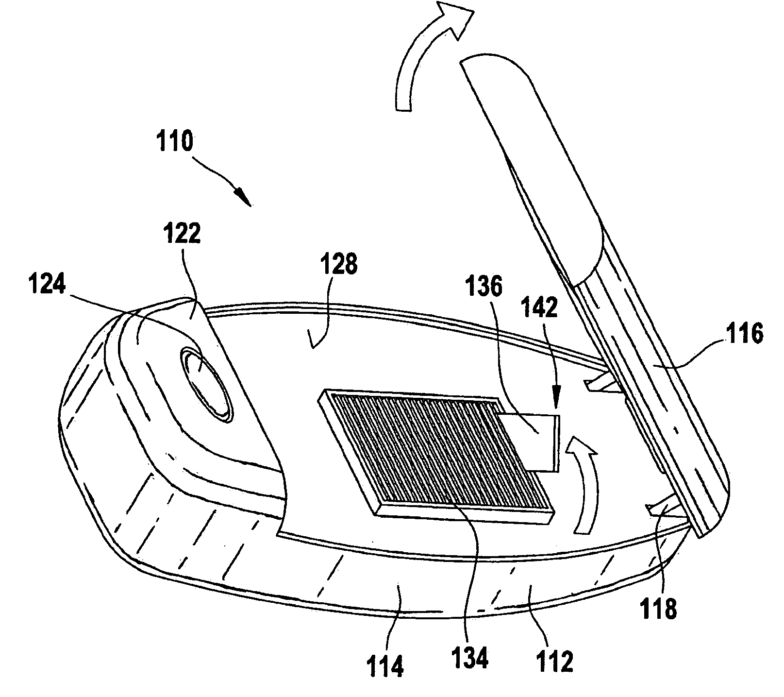
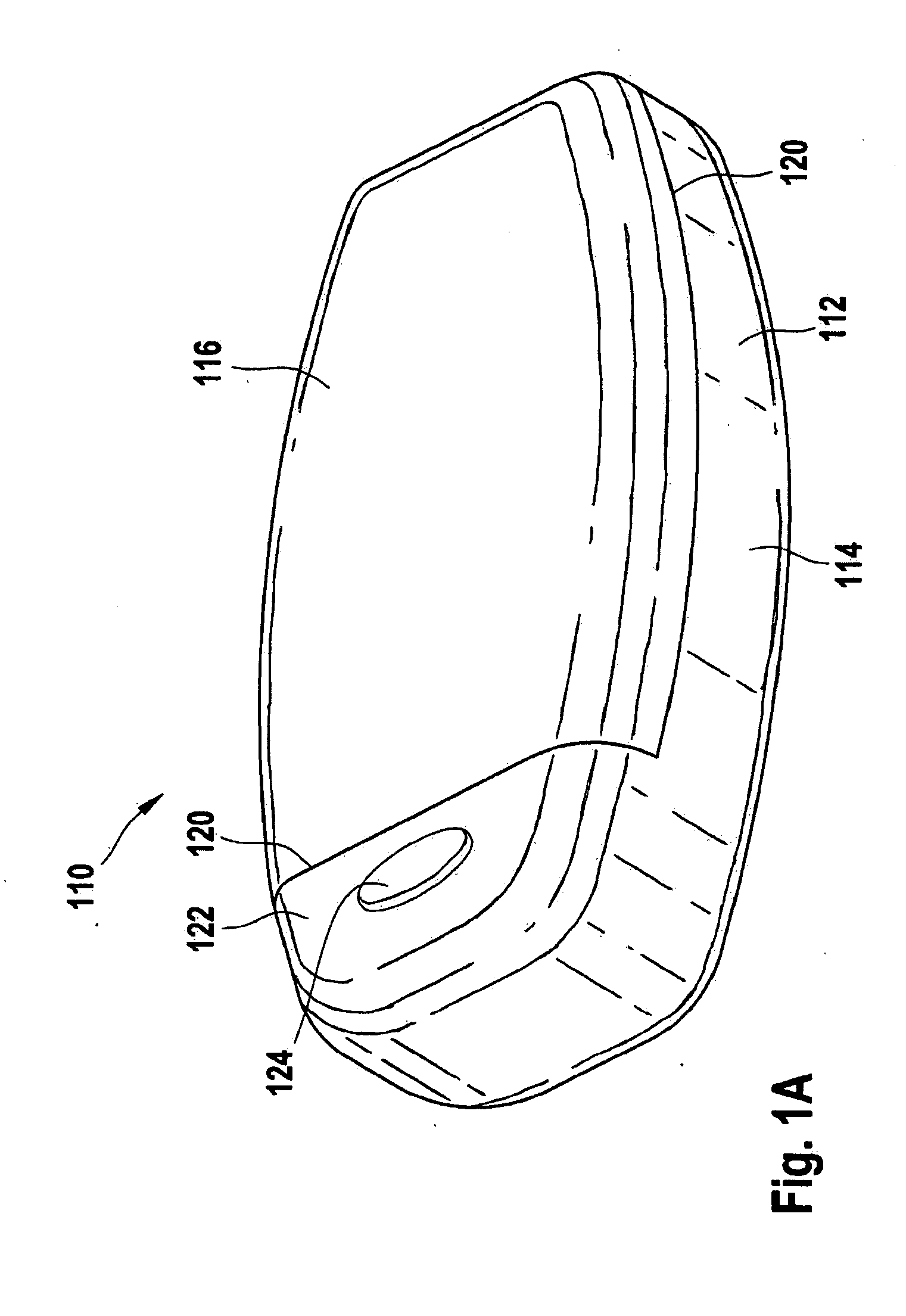
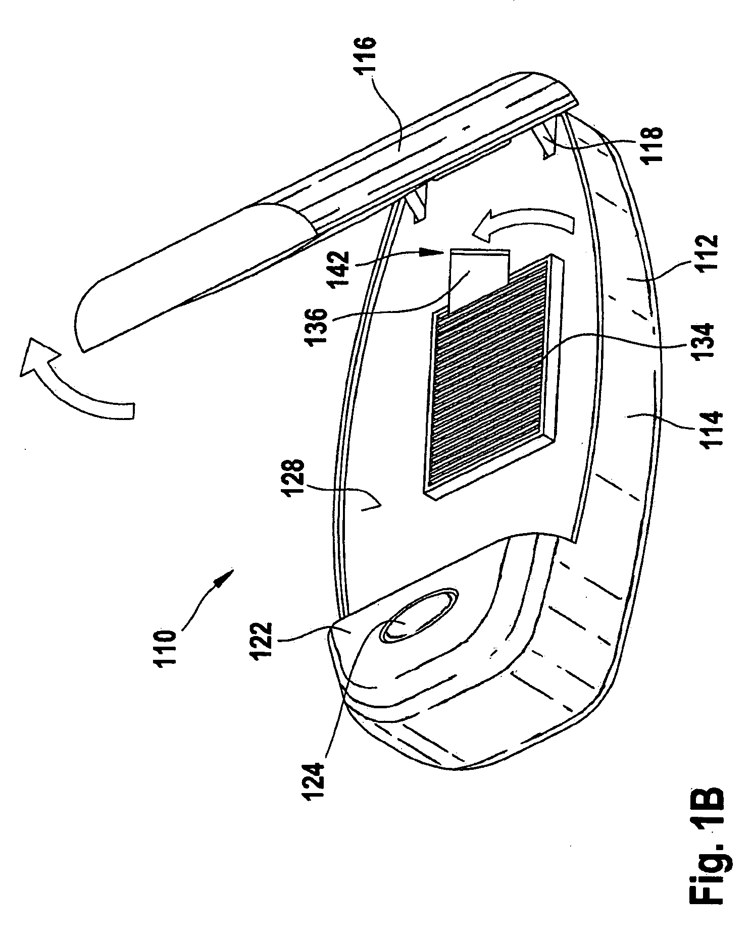
[0054]A first illustrative embodiment of a test device 110 according to the invention for determining a blood glucose concentration is shown in FIGS. 1A to 1C. FIG. 1A shows the test device 110 in the closed state, FIG. 1B shows the test device 110 during opening, and FIG. 1C shows the test device 110 in the opened state.

[0055]In one embodiment, the test device 110 comprises a housing 112 with a bottom part 114 and a lid 116 (upper part of housing). The bottom part 114 and the lid 116 are connected to each other along a hinge 118, said hinge 118 at the same time being configured, in other embodiments, to translate force. This translation of force allows the force applied for opening the lid 116 to be used in means provided in the bottom part 114 of the housing for rotating a test strip (see below).

[0...


PUM

PropertyMeasurementUnit
lengthaaaaaaaaaa
concentrationaaaaaaaaaa
opticalaaaaaaaaaa

Abstract

A test device for determining the concentration of at least one analyte in a sample using a element is proposed. The test device can be used particularly for glucose measurement, in particular blood glucose measurement, cholesterol measurement and / or coagulation measurement. The test device according to the invention comprises a housing with a closed state and an opened state, and a storage device for receiving at least one test element. The at least one test element is typically designed as a strip-shaped test element, and the storage device typically comprises a magazine. The magazine comprises a plurality of cavities, and the test elements are received substantially parallel to one another in the cavities. A measuring device and a dispensing device are also provided. The dispensing device comprises means for conveying the at least one test element from at least one storage position of the storage device during opening of the housing.

Description

PRIORITY CLAIM[0001]This application is a continuation of PCT Application No. PCT / EP2006 / 063208 filed Jun. 14, 2006, which claims the priority benefit of European Patent Application No. 05013396.6 filed Jun. 22, 2005.FIELD OF THE INVENTION[0002]The invention relates to a test device, in particular a portable test device, for determining at least one analyte concentration in a sample by means of a test element. The invention further relates to a test element for determining at least one analyte concentration in a sample using a test device according to the invention.BACKGROUND[0003]The monitoring of blood glucose concentration is an essential part of the daily routine of diabetics. The blood glucose concentration has to be determined quickly and reliably several times a day in order, if appropriate, to be able to take suitable medical measures. So as not to restrict the diabetic's daily routine any more than is necessary, suitable portable devices are often employed which are intende...

Claims


Application Information

Patent Timeline
Patent Type & Authority Applications(United States)
IPC IPC(8): B01J19/00B01L11/00G01N27/26B01L99/00
CPCG01N33/48757Y10T436/111666Y10T436/11Y10T436/112499Y10T436/144444
Inventor BAINCZYK, GREGOREISELE, THOMASWIEDER, HERBERT
Owner ROCHE DIABETES CARE INC
Learn More