
Step-up DC/DC voltage converter with improved transient current capability

a voltage converter and transient current technology, applied in the direction of electric variable regulation, process and machine control, instruments, etc., can solve the problems of inductive switching regulators, capacitive charge-pump converters, linear regulators, etc., and achieve the difficulties of extremely narrow pulse widths of buck and boost converters, for exampl

Inactive Publication Date: 2009-04-23
ADVANCED ANALOGIC TECHNOLOGIES INCORPORATED
View PDF12 Cites 122 Cited by
  • Summary
  • Abstract
  • Description
  • Claims
  • Application Information

AI Technical Summary

Benefits of technology

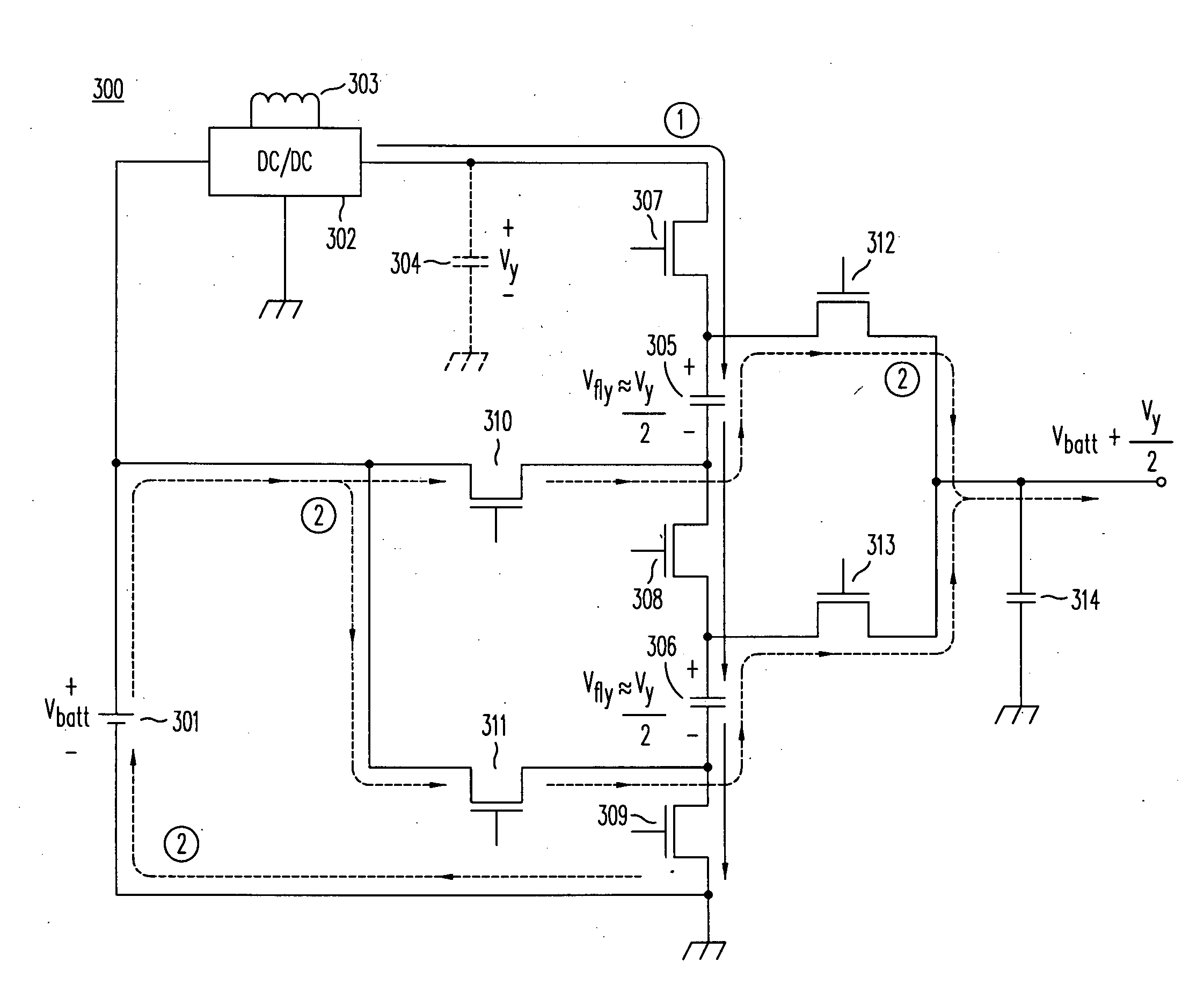
[0042]A DC / DC converter of this invention is able to supply relatively large transient currents in response to the demands of the load because the transient current capability of the converter is not affected by the series resistance of the pre-regulator.

Problems solved by technology

Prior art inductive switching regulators, capacitive charge-pump converters, and linear regulators, however, all suffer from certain limitations in capability and performance.
Inductive switching regulators suffer from a variety or fundamental limitations.
Both Buck and boost converters, for example, exhibit difficulties with extremely narrow pulse widths.
This narrow pulse limitation makes it difficult and inefficient to step an input voltage up by a high ratio—for example, by a factor of four or more.
Transferring more energy in a shorter duration requires increasingly higher currents, and efficiency suffers.
Because the low side MOSFET must turn off and then turn back on very quickly, extremely high duty cycles in a boost converter create a narrow off pulse problem, and degrade efficiency for high step up conversion ratios.
Regardless of whether the converter is a step-up or step-down converter, prior art converters suffer from a problem referred to as dropout.
Specifically, whenever the input voltage and the output voltage approach one another within the range of several hundred millivolts, i.e. Vout≈Vin±200 mV, the regulating ability of the converter suffers.
Another type of step-down converter, the linear regulator also suffers dropout and loss of regulation whenever the ΔV across the linear regulator's input and output terminals becomes too small.
So while linear regulators are not switching and are not limited by the narrow pulse problem, they still suffer from dropout effects and a corresponding loss of regulation.
Moreover, by itself, the linear regulator is only capable of step down operation.
Compared to their non-isolated counterparts, isolated converters such as the flyback and forward converter are able to operate at high efficiencies near unity conversion without the need switching modes or suffering dropout, but their use of physically-large tapped inductors, coupled inductors, and transformers precludes their application in most portable products.
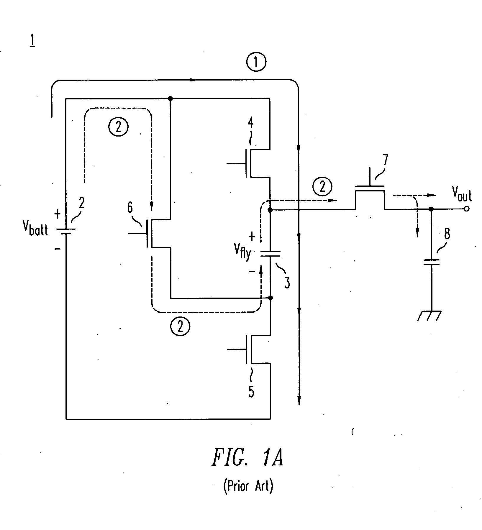
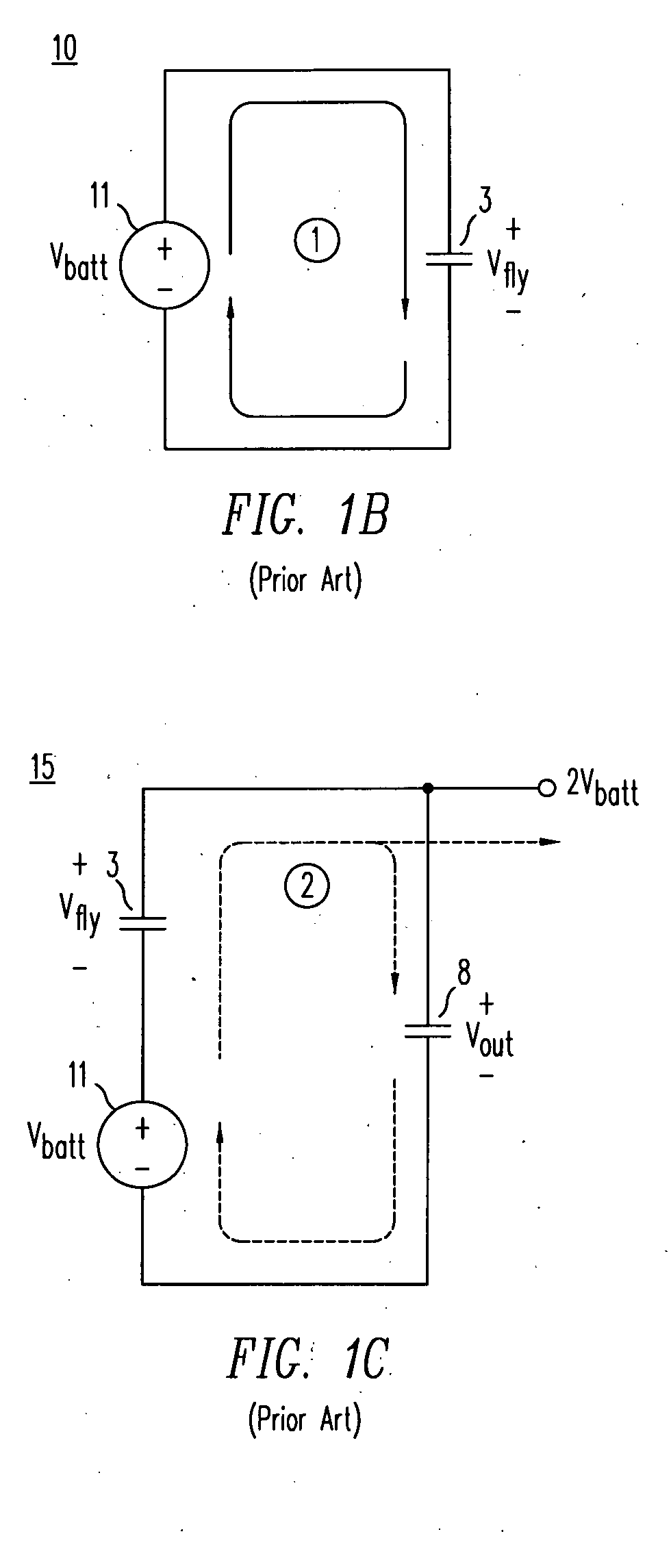
While a large variety of prior-art charge pumps exist, utilizing any number of flying capacitors and MOSFET switching networks, this type of converter can be pre-configured to either step-up or step-down a voltage but cannot be pre-configured to do both step-up and step-down conversion.
In some applications producing an output double the input voltage may be excessively high for the electrical load being powered.
In such an event, the efficiency of charge pump 1 can be very low.
One disadvantage of a charge pump is that it can only efficiently operate at specific conversion ratios.
If the output voltage is other than a select multiple of the input voltage, the converter exhibits a low efficiency.
Since the efficiency of the charge pump converter drops whenever the output-to-input voltage conversion ratio deviates from these specific voltage conversion ratios, it is not capable of generating a predetermined output voltage without significantly sacrificing efficiency.
Adapting a charge pump to produce a fixed output voltage as the input voltage varies, e.g. by forcing the output of the charge pump to a lower voltage by partially charging the flying capacitors, invariably sacrifices efficiency.
For that reason, charge pumps do not make efficient voltage regulators.
Of the available prior art converters, Buck converters and linear regulators can only offer step down conversion.
Furthermore, they lose regulation, i.e. suffer dropout, whenever the input and output voltages are similar.
For large differences in input and output voltages, linear regulators also suffer from poor efficiencies.
The boost converter is able to step-up an input voltage but with a number of limitations.
In addition to suffering dropout when Vin≈Vout and the duty factor approaches 100% due to the narrow pulse problem, the inductive boost converter is also limited whenever the duty factor approaches zero.
At such a condition, a boost converter's ability to step up an input voltage by a large multiple is limited from extremely narrow pulses of high currents, degrading efficiency and limiting its ability to regulate against transients.
They are not practical for general voltage regulation.
Any deviation from a predetermined multiple results in significant loss of efficiency.
In short, all present day non-isolated converters are limited in performance whenever their output and input voltages differ greatly.
Except for charge pumps, which do not provide an efficient means of regulation, the prior-art DC-to-DC converters may also become unstable or lose regulation when Vin≈Vout, i.e. approaching unity conversion ratios.
The choices for step-up conversion are even more limited since only boost converters or charge pumps provide non-isolated step up conversion in a small space.
Boost converters, however, suffer from high MOSFET currents and low efficiency at high conversion ratios.
Charge pumps cannot provide regulation without sacrificing efficiency.

Method used


Image

  • Step-up DC/DC voltage converter with improved transient current capability
  • Step-up DC/DC voltage converter with improved transient current capability
  • Step-up DC/DC voltage converter with improved transient current capability

Examples


Embodiment Construction

[0063]A new family of high-efficiency DC-to-DC converters and switching regulators is disclosed in Applications Nos. 11 / 890,818, 11 / 890,941, 11 / 890,956, and 11 / 890,994, all of which were filed on Aug. 8, 2007, and all of which are incorporated herein by reference. These converters feature the capability of dynamic up-down conversion and large voltage conversion ratios without the complication of mode switching, instability, over a wide range of operating conditions.

[0064]The converters disclosed therein combine an inductive energy storage element, denoted by L, with one or more continuously-switched capacitive storage elements, denoted by C. In one embodiment, referred to herein as a class of LCXU converter, a two-stage voltage converter comprises an inductive switching pre-regulator followed by a capacitive voltage post-converter. The inductive pre-regulator may either step-up or step-down the input voltage. The capacitive post-converter steps up the voltage at its input terminal, ...


PUM


Abstract

A DC / DC voltage converter includes an inductive switching voltage regulator and a capacitive charge pump connected in series between the input and output terminals of the converter. The charge pump has a second input terminal connected to the input terminal of the converter. This reduces the series resistance in the current path by which charge is transferred from the capacitor in the charge pump to the output capacitor and thereby improves the ability of the converter to respond to rapid changes in current required by the load.

Description

CROSS-REFERENCE TO RELATED APPLICATIONS[0001]This application is a continuation-in-part of application Ser. No. 11 / 890,818 and application Ser. No. 11 / 890,956, each of which was filed on Aug. 8, 2007, and is incorporated herein by reference in its entirety.BACKGROUND OF THE INVENTION[0002]This invention pertains to the design, operation and performance of switching power supplies for use in DC / DC conversion and voltage regulation, and to the semiconductor components used in such converters. Specifically, this invention focuses on step-up DC / DC conversion, i.e. where the output voltage exceeds the input voltage, and especially on DC / DC conversion wherein the output voltage is significantly greater than the minimum input voltage.[0003]Voltage regulation is commonly required to prevent variation in the supply voltage powering various microelectronic components such as digital ICs, semiconductor memories, display modules, hard disk drives, radio frequency (RF) circuitry, microprocessors...

Claims


Application Information

Patent Timeline
Patent Type & Authority Applications(United States)
IPC IPC(8): G05F1/10
CPCH02M3/07Y02B70/1466H02M2001/007H02M3/1588Y02B70/10H02M1/007H02M3/155G05F1/10
Inventor WILLIAMS, RICHARD K.
Owner ADVANCED ANALOGIC TECHNOLOGIES INCORPORATED
Learn More