Image forming apparatus

a technology of forming apparatus and nozzle, which is applied in the direction of printing, etc., can solve the problems of unintended nozzle leakage, failure of ejection, failure of discharge, etc., and achieve the effects of reducing layout restrictions, ensuring the capacity of common channels, and controlling mutual interference with efficiency

Active Publication Date: 2009-04-23
RICOH KK
View PDF18 Cites 52 Cited by
  • Summary
  • Abstract
  • Description
  • Claims
  • Application Information

AI Technical Summary

Benefits of technology

[0045]According to the above-described image forming apparatus, it is possible to provide the common channel separately from the channel member, so that it is possible to ensure capacity of the common channel. Further, since the deformable part serving as a wall face of the damper chamber is prevented from being exposed to the outside, layout restrictions are reduced. Further, it is possible to absorb a pressure variation and to control mutual interference with efficiency.

Problems solved by technology

If this pressure variation propagated to the common liquid chamber propagates back to the pressure liquid chamber discharging droplets of the liquid, the pressure variation varies the pressure of the pressure liquid chamber so as to prevent the pressure liquid chamber from discharging liquid droplets at a required droplet velocity with a required droplet amount (droplet volume), thus causing ejection failure (discharge failure).
Further, if mutual interference, where the pressure variation propagated to the common liquid chamber propagates to an adjacent pressure liquid chamber to affect its liquid, occurs, leakage or discharge of liquid droplets from unintended nozzles and destabilization of a discharge condition are induced.
However, in the case of providing a foamed flexible material or forming a damping structure in a common liquid chamber as disclosed in Patent Documents 1 and 2, there is difficulty in processing, and the cost of parts is high.
For example, it is difficult to process and dispose the foamed flexible material.
Further, as the driving frequency and the number of nozzles increase, the common liquid chamber pressure tends to increase, thus causing a problem in that it is difficult to ensure absorption and damping of the increasing pressure.
This narrows the range of choices for material, which may lead to a further increase in the cost of parts.
Further, in the case of providing a damper chamber as disclosed in Patent Documents 3 and 4, it is necessary to perform processing to form the damper chamber, and the increase in part size causes an increase in the cost of parts.
However, controlling the amount of air in the damper chamber is itself difficult, and there is a problem in that if air separated from the damper chamber turns into bubbles to enter a pressure liquid chamber, it is impossible to sufficiently increase the pressure in the pressure liquid chamber, which may result in ejection failure or cause no liquid droplets to be discharged.
Further, according to the head disclosed in Patent Document 4, since each ink reservoir chamber is formed on one side of the corresponding pressure generation chambers, and the damper recess parts are disposed next to the corresponding ink reservoir chambers with the diaphragm provided therebetween, it is difficult to ensure a large capacity for each ink reservoir chamber.
In particular, in the case of an elongated head such as a line-type head, timely replenishment or supply may not be possible.
Further, an increasing pressure variation per unit time in a head can no longer be managed by forming, on a wall face of a common liquid chamber, a damper surface of a pressure absorber that is lower in rigidity than the other wall faces and absorbs pressure through vibration as disclosed in Patent Documents 5 through 7.
That is, if the pressure absorbing effect of the common liquid chamber is weak in the above-described configuration, as the instantaneous pressure variation becomes greater as in the case of high-frequency driving or discharging large droplets, a greater delay in supplying recording liquid into the common liquid chamber is caused by the pressure.
This may prevent recovery of a meniscus so as to cause ejection failure.
However, in the configuration where the damper surface of the common liquid chamber deforms and vibrates in order to absorb the pressure in the common liquid chamber, if the vibration of the damper surface is not completely damped, the vibration of the damper surface causes a pressure variation so that the meniscus does not completely recover at the time of discharging a droplet.
This phenomenon makes it difficult to control a nozzle meniscus and causes undesirable variations in the volume, velocity, and discharge direction of a discharged droplet, thus preventing improvement of image quality.
However, before the vibration of the damper surface is damped, the volume and / or velocity of a discharged droplet may slightly vary at the vibration period of the vibration of the damper surface so as to degrade image quality.
Further, according to the head disclosed in Patent Document 5, since a wall face of the common liquid chamber is formed of a damper surface of a pressure absorber, the area of the thin film part increases, in particular, in an elongated head such as a line-type head, it is difficult for the thin film to maintain rigidity as a part the same as in the head disclosed in Patent Document 11, which leads to a decrease in assembly ability.
Further, in the case of providing a member having rubber elasticity on at least a wall of a reservoir that supplies liquid to multiple channels as disclosed in Patent Document 8, a longer time is necessary before the vibration of the wall face is damped because of reception of a repulsive force generated by the rubber-elasticity member in addition to the above-described problem in the case of absorbing a pressure variation in the common liquid chamber through the vibration of a damper surface.
As a result, the volume and / or velocity of a discharged droplet slightly varies at the vibration period of the vibration of the wall face, thus degrading image quality.
However, since this damper chamber is closed, an elongated head such as a line-type head particularly has a problem in that a sufficient buffer effect is not produced for a relatively large pressure variation caused in the case of applying energy to multiple pressure liquid chambers, thus causing unstable discharge.
However, since the surface of the thin film has to be in contact with the atmosphere according to this configuration, there is the problem of a greater number of layout restrictions.
Further, since the thin film is exposed, there is a problem in that a recording medium and the inkjet recording head may contact each other for some reason (such as a jam) to damage the thin film, thereby causing an outflow of liquid in the common liquid chamber.
Particularly, in an elongated head such as a line-type head, the thin film has a large area so that it is difficult for the thin film to maintain rigidity as a part, which leads to a decrease in assembly ability.
According to the head disclosed in Patent Document 12, providing the damper mechanism for absorbing pressure in the common liquid chamber makes the assembling process of the head complicated.

Method used


Image

  • Image forming apparatus
  • Image forming apparatus
  • Image forming apparatus

Examples


first embodiment

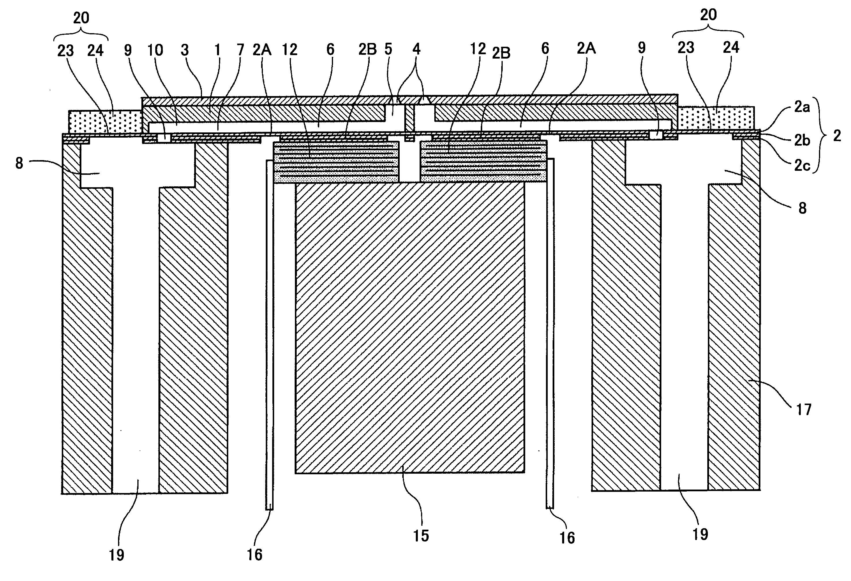
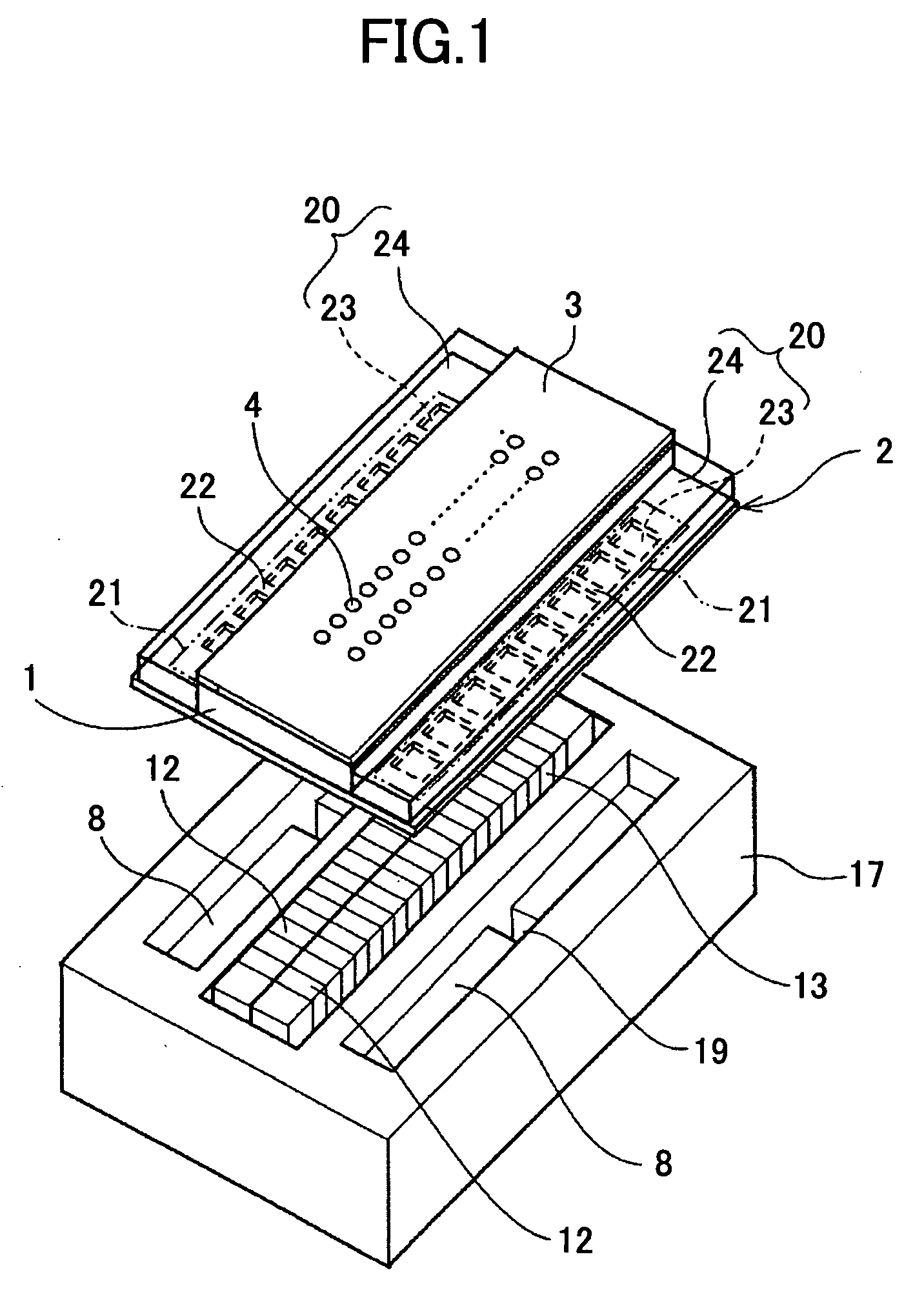
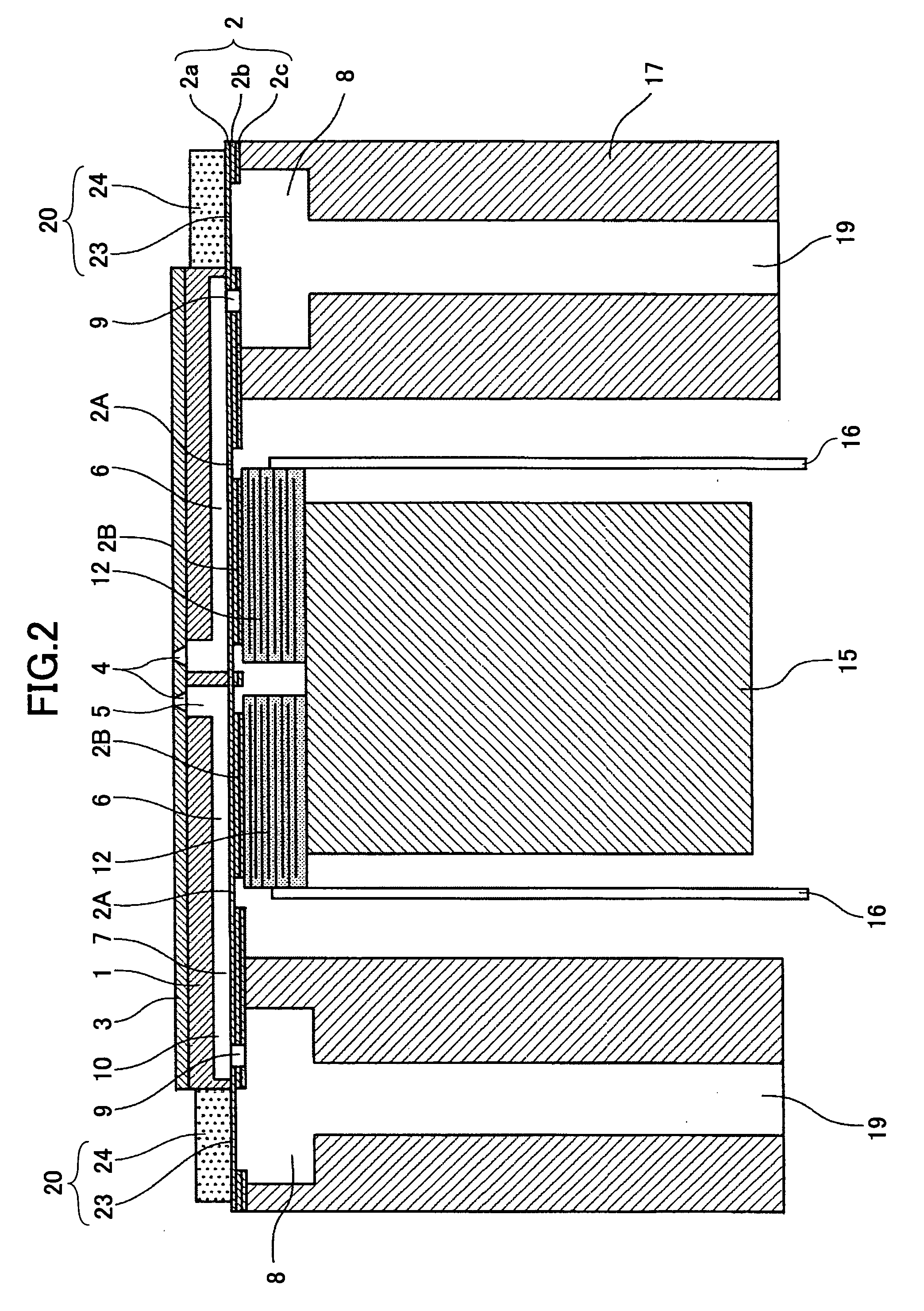
[0087]First, a description is given, with reference to FIGS. 1 through 3, of a liquid discharge head according to a first embodiment of the present invention. FIG. 1 is an exploded perspective view of the liquid discharge head. FIG. 2 is a cross-sectional view of the liquid discharge head taken along the length of a pressure liquid chamber of the liquid discharge head (the directions perpendicular to the directions in which nozzles are arranged). FIG. 3 is a longitudinal-sectional view of the liquid discharge head taken along the width of the pressure liquid chamber of the liquid discharge head (the directions in which the nozzles are arranged).

[0088]The liquid discharge head includes a channel plate (liquid chamber base plate) 1, a diaphragm member 2 joined to the lower surface of the channel plate 1, and a nozzle plate 3 joined to the upper surface of the channel plate 1, thereby forming pressure liquid chambers (also referred to as “pressure chambers” or “channels”) 6 serving as ...

second embodiment

[0121]Next, a description is given, with reference to FIG. 5, of a liquid discharge head according to a second embodiment of the present invention. FIG. 5 is a cross-sectional view of the liquid discharge head taken along the length of a pressure liquid chamber of the liquid discharge head. In FIG. 5, the same elements as those of the first embodiment are referred to by the same reference numerals.

[0122]This head includes a nozzle cover 31 that protects the periphery of the nozzle plate 3. The nozzle cover 31 also serves as a member to protect the damper parts 20.

[0123]The nozzle cover 31 can protect the damper parts 20 from contact with the outside or contamination, so that it is possible to prevent damage to the liquid discharge head and degradation of its characteristics. Here, examples of “contact with the outside” includes contact with other parts, an assembler, jigs, and human hands during a manufacturing process and contact with paper due to a paper jam in an image forming ap...

third embodiment

[0124]Next, a description is given, with reference to FIG. 6, of a liquid discharge head according to a third embodiment of the present invention. FIG. 6 is a cross-sectional view of the liquid discharge head taken along the length of a pressure liquid chamber of the liquid discharge head. In FIG. 6, the same elements as those of the first embodiment are referred to by the same reference numerals.

[0125]This head includes a protection layer 32 that covers the surface of the damper material 24. The protection layer 32 may be formed by depositing fluororesin (such as pitch fluoride) or by baking or setting with ultraviolet rays a solvent of a silicon-based resin, a fluorine-based resin, an epoxy resin, or polyimide after its application. It is preferable that the protection layer 32 be a solid with tack in terms of easiness of handling in manufacturing the head. Further, it is preferable that the protection layer 32 have resistance to liquid (resistance to ink).

[0126]By thus protecting...


PUM


Abstract

An image forming apparatus is disclosed that includes a liquid discharger including a liquid discharge head configured to discharge a droplet of liquid so as to form an image. The liquid discharge head includes multiple individual channels communicating with corresponding nozzles from which the liquid is discharged; a common channel configured to supply the liquid to the individual channels; a deformable member configured to form at least one wall face of the common channel; and a vibration damping member formed of a viscoelastic material, the vibration member being provided in contact with the deformable member.

Description

BACKGROUND OF THE INVENTION[0001]1. Field of the Invention[0002]The present invention relates to an image forming apparatus.[0003]2. Description of the Related Art[0004]Some common image forming apparatuses such as printers, facsimile machines, copiers, plotters, and those having two or more of the functions of these apparatuses perform image forming (recording or printing) by causing recording liquid (hereinafter also referred to as “ink”) as liquid to adhere to a medium (hereinafter also referred to as “paper” or “paper sheet,” but not limited to paper in material; “medium to be subjected to recording,”“recording medium,”“transfer material,” and “recording paper” may also be used as synonyms) while conveying the paper, using, for example, a liquid discharger (liquid discharge device) including a recording head formed of a liquid discharge head that discharges liquid droplets of the recording liquid.[0005]The term “image forming apparatus” means an apparatus that performs image for...

Claims


Application Information

Patent Timeline
Patent Type & Authority Applications(United States)
IPC IPC(8): B41J2/17
CPCB41J2/055B41J2002/14419B41J2/14274
Inventor YAMANAKA, KUNIHIROHASHIMOTO, KENICHIROHMAKITA, HIDEYUKIYOSHIDA, TAKAHIROMIURA, KUNIHIROSASAKI, TAKAFUMIYAMAGUCHI, KIYOSHI
Owner RICOH KK
Why Eureka
Try Eureka