Opitcal pickup

a technology of optical pickup and optical axis, which is applied in the field of optical pickup, can solve the problems of deteriorating an error rate in reading data, unbalanced tracking signal, and jitter in the rf signal, so as to reduce the jitter of a data signal, improve the reliability of read data, and reduce the effect of reflected light from an adjacent layer

Inactive Publication Date: 2009-04-23
HITACHI MEDIA ELECTORONICS CO LTD
View PDF2 Cites 9 Cited by
  • Summary
  • Abstract
  • Description
  • Claims
  • Application Information

AI Technical Summary

Benefits of technology

[0009]The variation of the intensity of the RF signal which is the whole quantity of the beam 811 causes the deterioration of jitter in the RF signal and deteriorates an error rate in reading data. Interference with the beams 812, 813 causes the variation of the TR signal. As the intensity of the subbeams generated by being split by a diffraction grating is set to a small value in design, the intensity is similar to the power density of the reflected light of the main beam from the adjacent layer and therefore, the effect of the interference is intensified. This interference is also influenced by the gradient and the layer-to-layer spacing of the optical disc and the intensity distribution in the beam spot 812 or 813 varies by the rotation of the disc having uneven layer-to-layer spacing. As a result, a part of a differential signal (E−F)+(G−H) of the TR signal is influenced and a tracking signal is unbalanced. Hereby, a problem that tracking is disabled occurs. Similarly, when the adjacent layer 512 is located on the side close to the objective lens of the target reading layer 511, reflected light is also caused from the adjacent layer and problematic interference is similarly caused.
[0010]An object of the invention is to reduce crosstalk to a data signal and a tracking signal caused from another layer when data stored on a multi-layer optical disc is read by an optical pickup.
[0011]A method of reducing the effect of reflection from another layer is used for addressing the above-mentioned problem.
[0013]The grating is overlapped with at least one of minimum spot positions by the reflected light condenser lens of the reflected light from another layer and is provided with the grating including an optical axis and with a direction of its grooves perpendicular to the optical axis or with the grating inclined from the optical axis. The grating plays a role of preventing reflected light from another layer from returning to the reflected light condenser lens.
[0014]According to the invention, only reflected light from the corresponding layer can be extracted and when the reflected light is detected by the photodetector, the effect of reflected light from an adjacent layer can be reduced. Hereby, the jitter of a data signal can be reduced and the reliability of read data is enhanced. When three beams are used, the quantity of reflected light from the adjacent layer incident on a subbeam detector can be reduced and the variation by interference of a tracking error signal can be reduced. Hereby, when data stored on an optical disc is read or data is written to the optical disc, a light spot never deviates from a track.

Problems solved by technology

The variation of the intensity of the RF signal which is the whole quantity of the beam 811 causes the deterioration of jitter in the RF signal and deteriorates an error rate in reading data.
As a result, a part of a differential signal (E−F)+(G−H) of the TR signal is influenced and a tracking signal is unbalanced.
Hereby, a problem that tracking is disabled occurs.
Similarly, when the adjacent layer 512 is located on the side close to the objective lens of the target reading layer 511, reflected light is also caused from the adjacent layer and problematic interference is similarly caused.

Method used


Image

  • Opitcal pickup
  • Opitcal pickup
  • Opitcal pickup

Examples


first embodiment

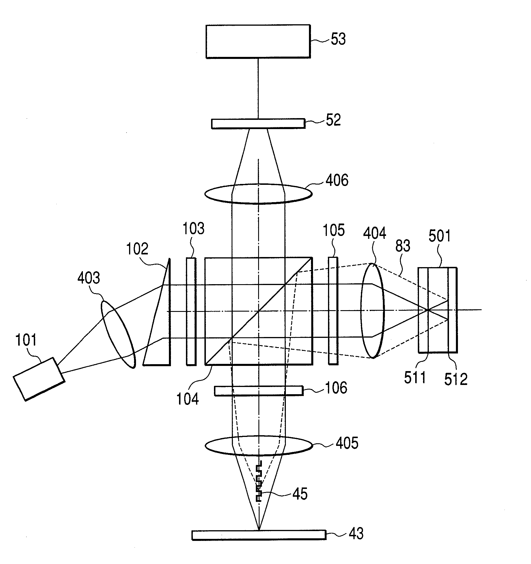
[0064]FIG. 1 shows an optical system of an optical pickup according to a first embodiment of the invention. A laser beam radiated from a semiconductor laser 101 is converted into a circular collimated light beam by a collimator lens 403 and a triangular prism 102. The collimated beam is split into three beams by a diffraction grating 103 to be one main beam and two subbeams. The traveling direction of the main beam is the same as that of an incident beam; however, the subbeams are turned outgoing beams having a certain gradient on both sides of an optical axis. Normally, difference in the quantity of light between the main beam and the subbeam is set to 10 times or more. The three beams are transmitted in a polarizing beam splitter 104, are converted into circularly polarized waves by a quarter-wave lambda plate 105, and are focused on a multi-layer disc 501 rotated by a rotating mechanism by an objective lens 404. In this case, a two-layer disc is shown as the multi-layer disc 501;...

second embodiment

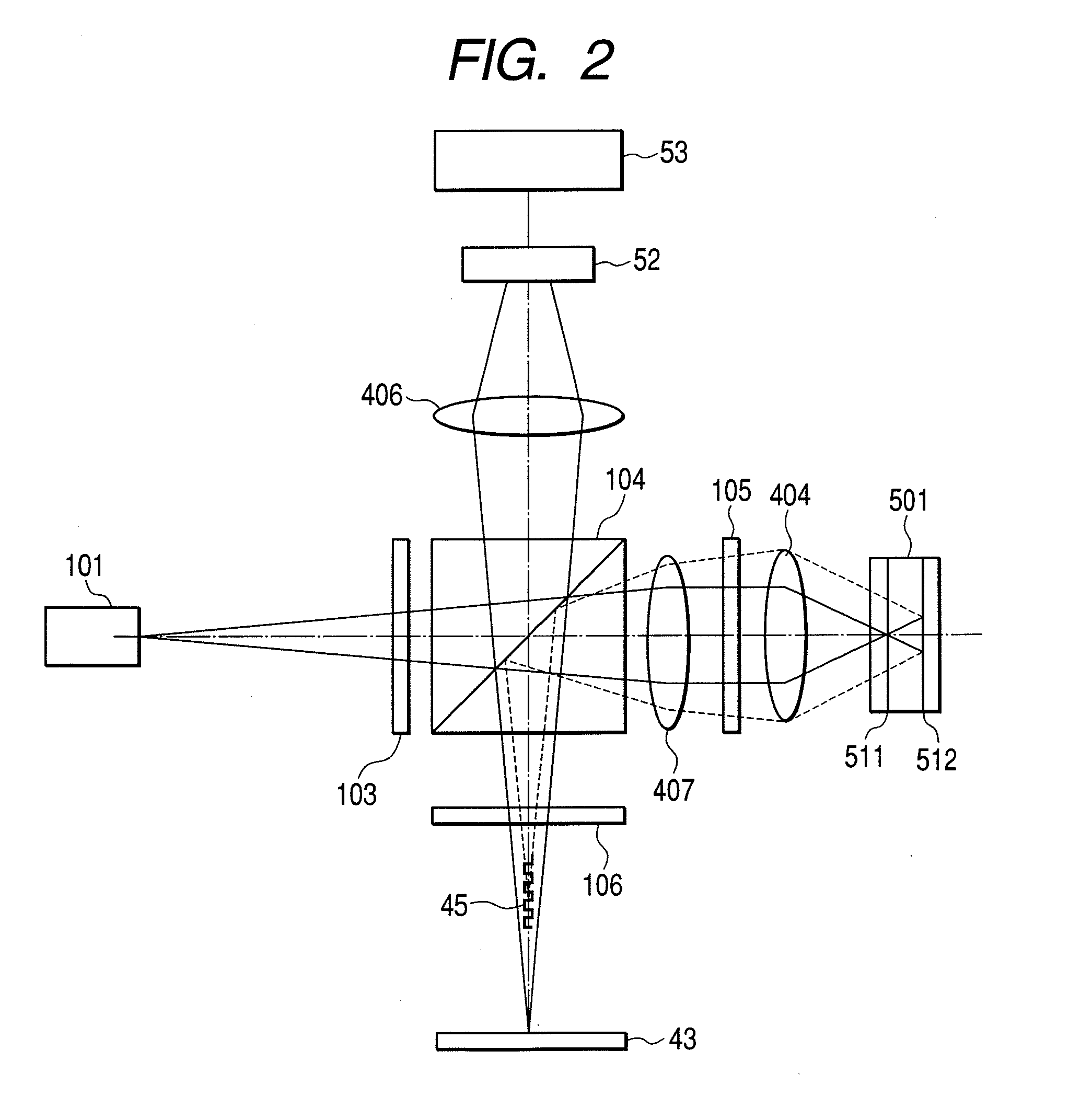
[0070]FIG. 2 shows an optical system of an optical pickup according to a second embodiment of the invention. In this embodiment, a diffraction grating 103 and a polarizing beam splitter 104 are installed on the side of a semiconductor laser 101 at the back of a collimator lens 407. Therefore, a laser beam outgoing from the semiconductor laser 101 is transmitted in the polarizing beam splitter 104 in a divergent state, afterward, is collimated by the collimator lens 407, and is incident on a quarter-wave lambda plate 105. In the first embodiment, as the diffraction grating 103 and the polarizing beam splitter 104 are installed between the collimator lens 403 and the objective lens 404, the condenser lens 405 is required; however, in the second embodiment, as shown in FIG. 2, as a light beam reflected from a reading layer 511 of a multi-layer disc 501 is converged through the collimator lens 407, no condenser lens is required. Hereby, effect that the number of parts can be reduced is ...

third embodiment

[0071]FIG. 22 shows an embodiment of an optical disc drive that can reduce the variation of a sub push-pull signal (SPP). Circuits 711 to 714 are provided to record data on a multi-layer optical disc 501. In the encoding circuit for error correcting 711, an error correcting code is added to data. The recording encoding circuit 712 modulates data according to a 1-7PP method. The recording compensating circuit 713 generates a pulse for writing suitable for mark length. A semiconductor laser in an optical pickup 60 is driven based upon a generated pulse string by the semiconductor laser driving circuit 714 and a laser beam 80 outgoing from an objective lens is modulated. A phase change film is formed on the optical disc 501 rotated by a motor 502, when the phase change film is heated and is rapidly cooled, it is turned amorphous, and when the phase change film is slowly cooled, it is turned crystalline. These two states are different in reflectance and a mark can be generated. As in wr...


PUM


Abstract

To reduce a bad influence on a tracking control signal and a data signal by reflected light from an adjacent layer on a multi-layer disc as stray light, the following device is made in the invention. Reflected light from the multi-layer optical disc including stray light from another layer is once converged by a reflected light condenser lens and is reflected on a reflector. A grating which prevents zero-order light from being generated by setting groove depth to λ / 4 and which is set to pitch to prevent positive and negative first- or higher-order diffracted lights from returning to the reflected light condenser lens is arranged between the lens and the reflector including an optical axis with the grating apart from the reflector. Hereby, as reflected light from another layer is cut off though reflected light from a corresponding layer is transmitted to a detector, a detected control signal and a detected data signal are not influenced by reflected light from another layer.

Description

CLAIM OF PRIORITY[0001]The present application claims priority from Japanese application JP 2007-273947 filed on Oct. 22, 2007, the content of which is hereby incorporated by reference into this application.FIELD OF THE INVENTION[0002]The present invention relates to an optical pickup, particularly relates to a reading optical system of the optical pickup.BACKGROUND OF THE INVENTION[0003]The storage capacity of one layer of an optical disc greatly depends upon a wavelength of a used semiconductor laser and a numerical aperture (NA) of an objective lens. The shorter the wavelength of the semiconductor laser is or the larger NA is, the larger the recording density can be and the capacity per one layer can be increased. The mainstream of optical disc drives currently distributed on the market is a digital versatile disc (DVD) drive using red light having a wavelength in the vicinity of 650 nm and an objective lens the NA of which is 0.6; however, as a drive the recording density of whi...

Claims


Application Information

Patent Timeline
Patent Type & Authority Applications(United States)
IPC IPC(8): G01B9/02
CPCG11B7/0906G11B2007/0013G11B7/1381G11B7/0943
Inventor KIMURA, SHIGEHARUIDE, TATSUROWATANABE, KOICHI
Owner HITACHI MEDIA ELECTORONICS CO LTD
Why Eureka
Try Eureka