
Reducing agent spray control system ensuring operation efficiency

a technology of spray control system and reducing agent, which is applied in the direction of fluid pressure control, separation process, instruments, etc., can solve the problems of increasing physical load and reducing service life, and achieve the effects of increasing the pressure accelerating the reaction of the selected component, and enhancing the atomization of the reducing agen

Inactive Publication Date: 2009-04-23
DENSO CORP
View PDF3 Cites 19 Cited by
  • Summary
  • Abstract
  • Description
  • Claims
  • Application Information

AI Technical Summary

Benefits of technology

[0009]It is another object of the invention to provide a reducing agent spray control system which controls an exhaust emission control device working to spray a reducing agent into an exhaust pipe of an internal combustion engine to induce a reduction reaction of a selected component of the exhaust gas with the reducing agent for converting the selected component into a harmless product and which is designed to ensure the efficiency of purification of the exhaust gas without sacrificing the service life of the exhaust emission control device.
[0011]The velocity at which the selected component of the exhaust gas reacts with the reducing agent is regulated by controlling the pressure of the reducing agent to be sprayed into the exhaust pipe. Specifically, an increase in pressure of the reducing agent will result in enhanced atomization of the reducing agent sprayed by the injector into the exhaust pipe, thereby accelerating the reaction of the selected component with the reducing agent. Such efficiency of purification of the exhaust gas is found to change with a change in state of the exhaust gas. The control means is, therefore, designed to set the pressure of the reducing agent to be sprayed by the injector to the target value, as determined based on the state of the exhaust gas. For instance, when the exhaust gas state parameter indicates a higher possibility that the efficiency of purification of the exhaust gas has been reduced, the control means elevates the pressure of the reducing agent to accelerate the reaction of the selected component with the reducing agent. Alternatively, when the exhaust gas state parameter indicates a lower possibility that the efficiency of purification of the exhaust gas has been reduced, the control means decreases the pressure of the reducing agent, thereby reducing a load on the pump to ensure the service life of the pump.

Problems solved by technology

The elevation of the pressure of the compressed air will, however, result in an increased physical load on the air pump which leads to a decrease in service life thereof.

Method used


Image

  • Reducing agent spray control system ensuring operation efficiency
  • Reducing agent spray control system ensuring operation efficiency
  • Reducing agent spray control system ensuring operation efficiency

Examples


second embodiment

[0051]The urea SCR device of the second embodiment will be described below.

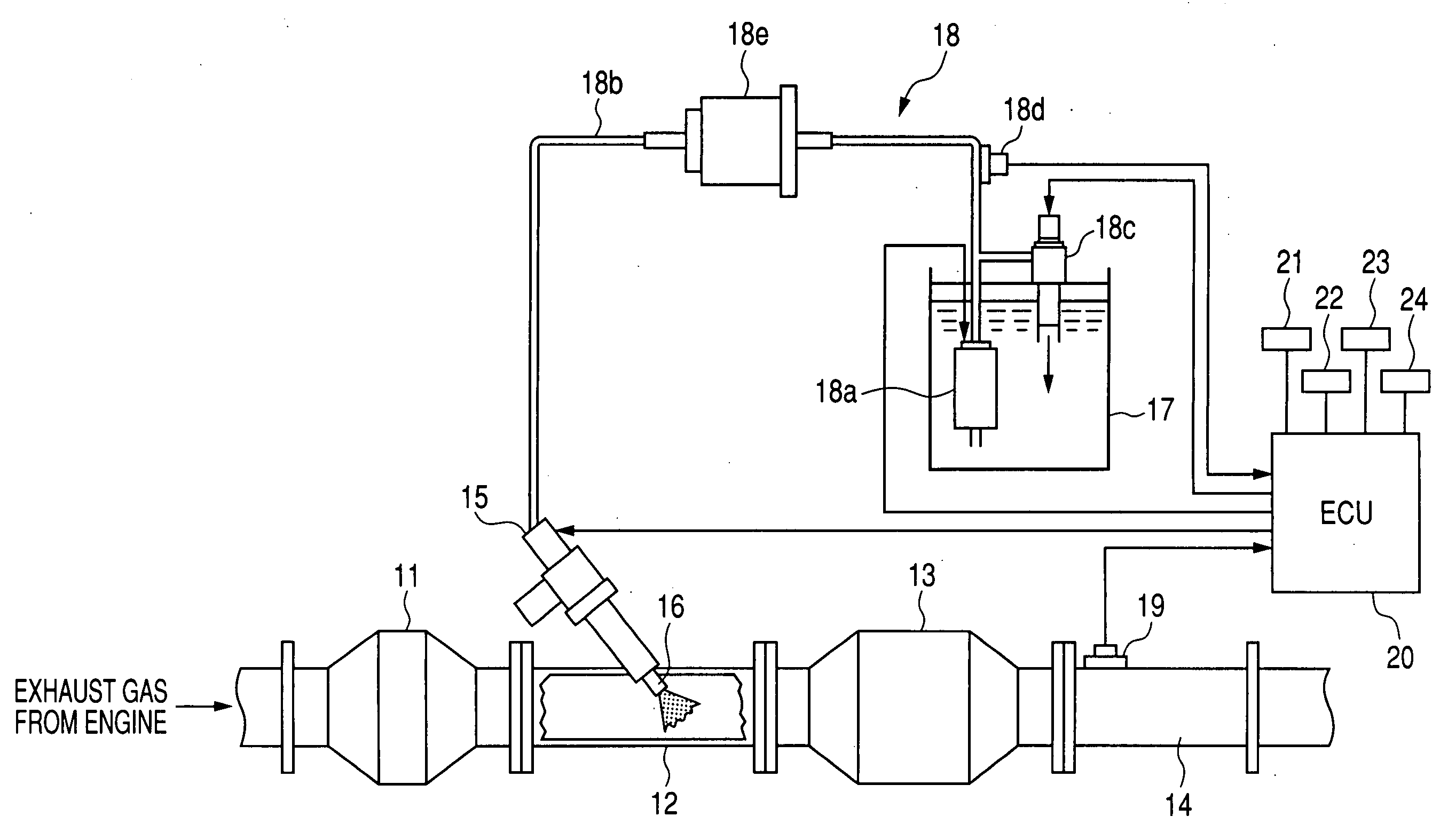
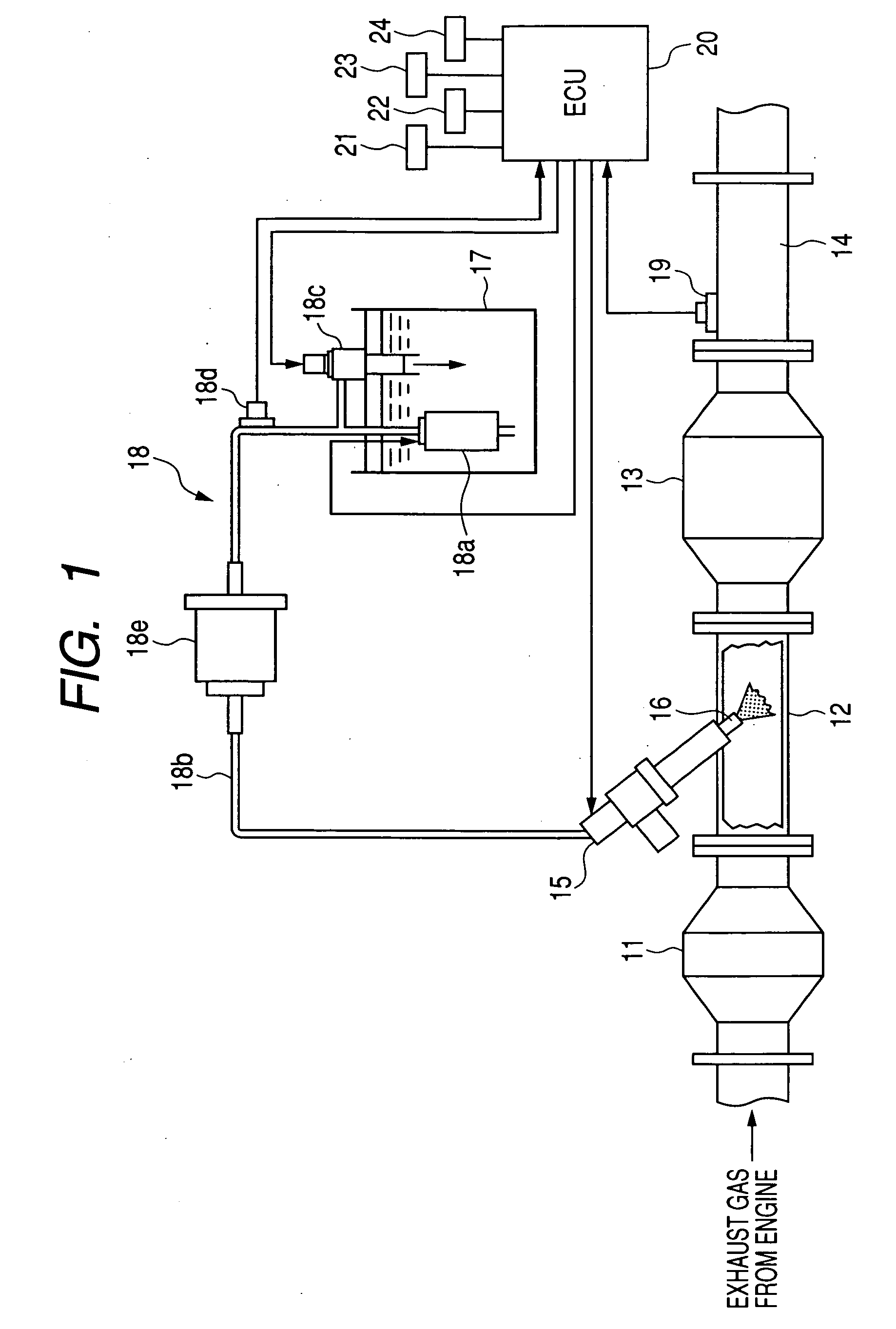
[0052]The ECU 20 of the urea SCR device of this embodiment is designed to control the injection pressure Pi of the urea aqueous solution as a function of the flow velocity (i.e., the flow rate) of the exhaust gas within the exhaust pipe of the diesel engine. This control task will be described below in detail with reference to a flowchart of FIG. 4. The same step numbers, as employed in FIG. 2, will refer to the same operations, and explanation thereof in detail will be omitted here.

[0053]After entering the program, the routine proceeds to step 20 wherein the flow velocity FVex of the exhaust gas emitted from the diesel engine is determined. The flow velocity FVex may be calculated using an output from the airflow meter 21.

[0054]The routine proceeds to step 21 wherein it is determined whether the flow velocity FVex is higher than or equal to a given threshold value FVs or not. If a YES answer is obtained mean...

third embodiment

[0059]The urea SCR device of the third embodiment will be described below.

[0060]The ECU 20 of the urea SCR device of this embodiment is designed to control the injection pressure Pi of the urea aqueous solution as a function of the quantity of NOx contained in the exhaust gas after cleaned by the SCR catalyst 13. This control task will be described below in detail with reference to a flowchart of FIG. 5.

[0061]After entering the program, the routine proceeds to step 30 wherein the quantity QTa of NOx contained in the exhaust gas flowing downstream of the SCR catalyst 13 is determined.

[0062]The routine proceeds to step 31 wherein it is determined whether the quantity QTa of NOx, as derived in step 30, is smaller than or equal to a threshold value QTs1 or not. If a YES answer is obtained meaning that the quantity QTa of NOx is smaller than or equal to the threshold value QTs1, then the routine proceeds to step 12 wherein the ECU 20 sets the injection pressure Pi of the urea aqueous sol...

fourth embodiment

[0066]The urea SCR device of the fourth embodiment will be described below.

[0067]The ECU 20 of the urea SCR device of this embodiment is designed to control the injection pressure Pi of the urea aqueous solution as a function of the quantity of NOx contained in the exhaust gas before cleaned by the SCR catalyst 13. This control task will be described below in detail with reference to a flowchart of FIG. 6.

[0068]After entering the program, the routine proceeds to step 40 wherein the quantity QTb of NOx contained in the exhaust gas flowing upstream of the SCR catalyst 13 is determined.

[0069]The routine proceeds to step 41 wherein it is determined whether the quantity QTb of NOx, as derived in step 40, is smaller than or equal to a threshold value QTs2 or not. If a YES answer is obtained meaning that the quantity QTb of NOx is smaller than or equal to the threshold value QTs2, then the routine proceeds to step 12 wherein the ECU 20 sets the injection pressure Pi of the urea aqueous sol...


PUM


Abstract

A reducing agent spray control system designed to control an exhaust emission control device such as a urea SCR device for automotive internal combustion engines. The exhaust emission control device includes an injector injecting a spray of a reducing agent into an exhaust pipe of the engine to reduce a selected component such as NOx in exhaust gas to purify the exhaust gas and a pump regulating the pressure of the reducing agent to be sprayed by the injector. The system works to control the pump so as to bring the pressure of the reducing agent to be sprayed by the injector into agreement with a target value, as determined based on the state of the exhaust gas, to ensure the efficiency of purification of the exhaust gas without sacrificing the service life of the pump.

Description

CROSS REFERENCE TO RELATED DOCUMENT[0001]The present application claims the benefit of Japanese Patent Application No. 2007-271983 filed on Oct. 19, 2007, the disclosure of which is incorporated herein by reference.BACKGROUND OF THE INVENTION[0002]1. Technical Field of the Invention[0003]The present invention relates generally to a reducing agent spray control system which may be employed with an SCR (Selective Catalytic Reduction) system for automotive internal combustion engines which works as an exhaust emission control device to spray a reducing agent such as a urea aqueous solution to induce an exhaust gas purification reaction.[0004]2. Background Art[0005]Urea SCR systems are now being developed which are designed as exhaust emission control systems for automotive internal combustion engines such as diesel engines to use a reducing agent such as a urea aqueous solution to convert NOx (nitrogen oxide) contained in exhaust gas into harmless or less harmful products effectively. ...

Claims


Application Information

Patent Timeline
IPC IPC(8): B01D53/92
CPCF01N3/021F01N3/2066F01N3/208F01N2560/026F01N2560/06F01N13/009F01N2610/02F01N2610/14F01N2610/146F01N2900/08Y02T10/24F01N2560/07Y02T10/12
Inventor ICHIKAWA, ATARU
Owner DENSO CORP
Learn More