

Power Supply Control Device and Method of Detecting Abnormality of Relay
a technology of power supply control device and relay, which is applied in the direction of electric devices, instruments, propulsion by batteries/cells, etc., to achieve the effect of preventing the generation of inrush curren
- Summary
- Abstract
- Description
- Claims
- Application Information
AI Technical Summary
Benefits of technology
Problems solved by technology
Method used
Image

Examples
first embodiment
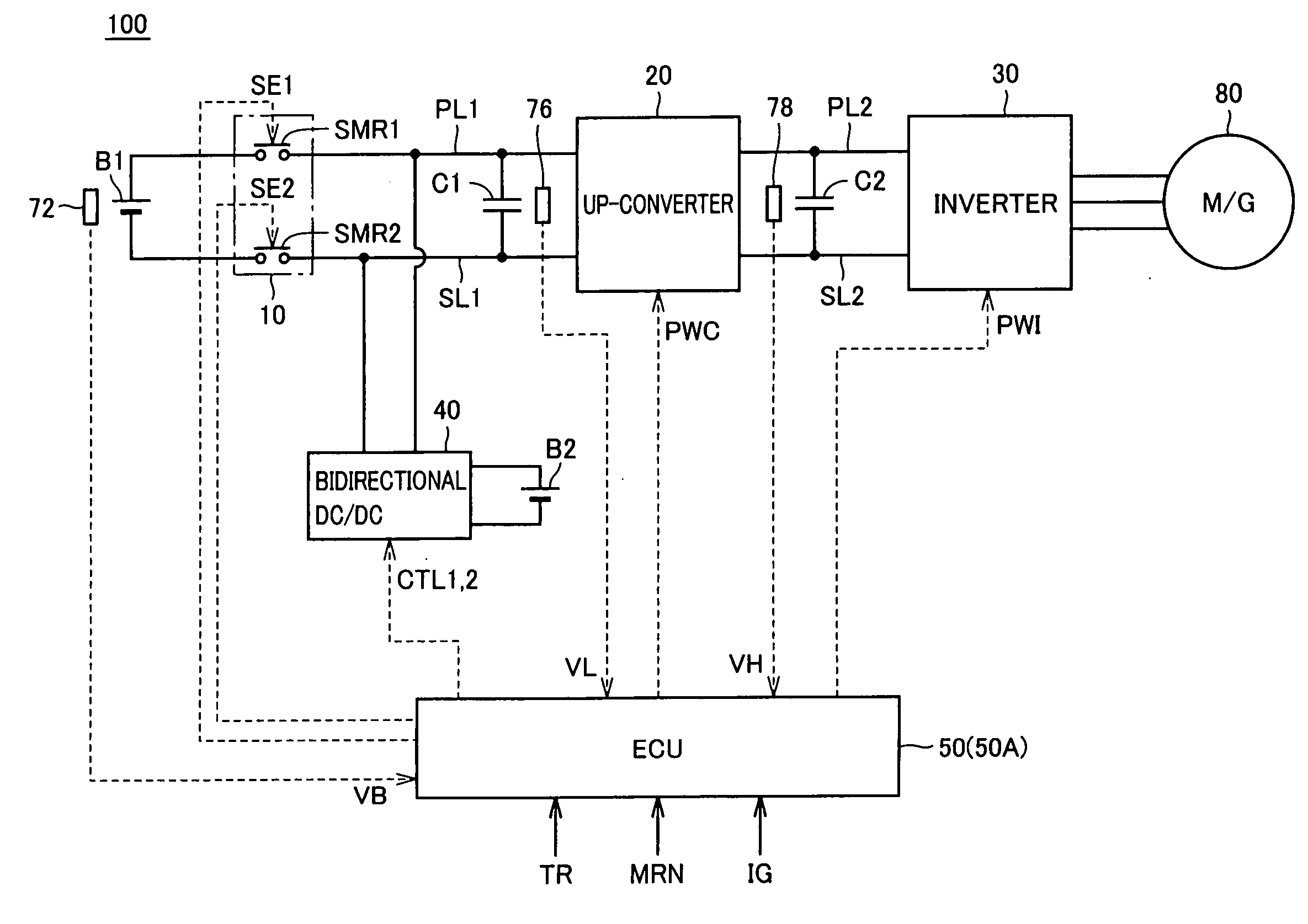
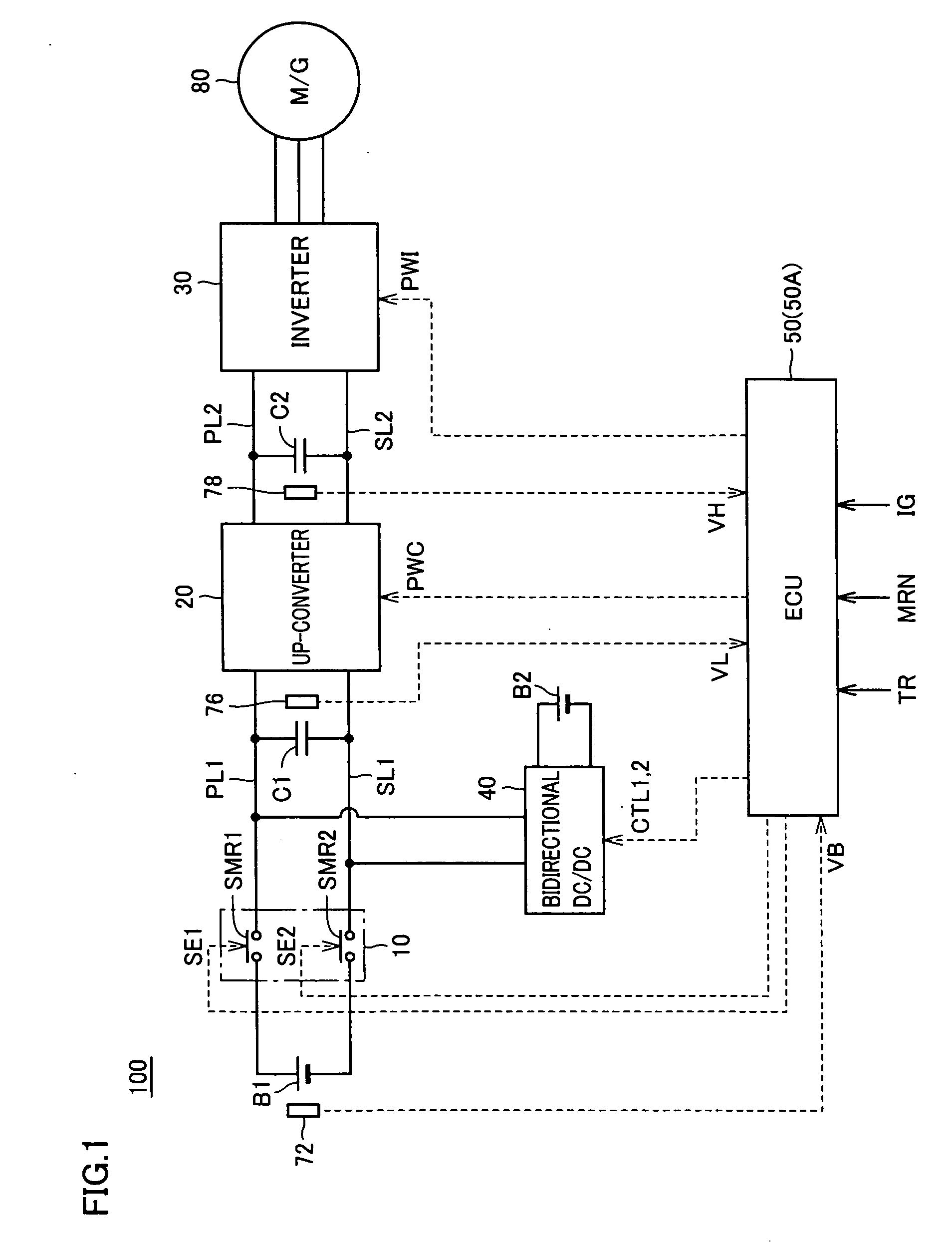
[0030]FIG. 1 is an entire block diagram of a load driving device including a power supply control device in accordance with a first embodiment of the present invention. Referring to FIG. 1, a load driving device 100 includes a main power storage device B1, a system main relay 10, an up-converter 20, an inverter 30, power supply lines PL1 and PL2, ground lines SL1 and SL2, capacitors C1 and C2, a bidirectional DC / DC converter 40, an auxiliary equipment power storage device B2, an ECU (Electronic Control Unit) 50, and voltage sensors 72, 76, and 78.
[0031]Load driving device 100 is mounted in an electrically driven vehicle such as a hybrid vehicle or an electric vehicle. A motor generator 80 driven by load driving device 100 is coupled with drive wheels (not shown), and mounted in a vehicle as an electric motor driving the drive wheels. Motor generator 80 may be coupled with an engine (not shown), and mounted in a hybrid vehicle as a device operating as an electric motor capable of sta...
second embodiment
[0073]A second embodiment has a configuration similar to that of the first embodiment except for the method of determining whether or not the relay is welded when the system is started.
[0074]FIG. 6 is a flow chart of control by an ECU 50A in the second embodiment when the system is started up. The process of the flow chart is also invoked from the main routine and executed at regular time intervals or every time when a prescribed condition is satisfied.
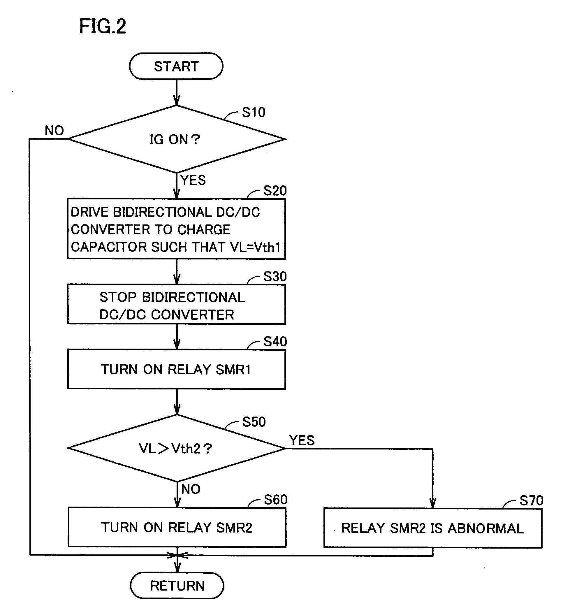
[0075]Referring to FIG. 6, the process shown in the flow chart includes steps S52 and S54 instead of step S50 in a series of steps shown in FIG. 2. Specifically, when the first stage precharging is performed in step S20 and relay SMR1 is turned on in step S40, ECU 50A generates signal CTL2, supplies it to bidirectional DC / DC converter 40, and activates signal CTL2 until when voltage VL reaches voltage VB (step S52).
[0076]During the second stage precharging in step S52, ECU 50A measures a time period Δt from when relay SMR1 is turned o...
PUM
 Abstract
Description
Claims
Application Information