Isolated current to voltage, voltage to voltage converter

a voltage converter and isolated current technology, applied in the direction of measurement devices, instruments, measurement using dc-ac conversion, etc., can solve the problems of increasing the complexity of the circuit, reducing the size and complexity of the magnetic circuit, and increasing the cost of the circuit, so as to reduce the cost and bulk of the sensor, the cost of a slightly more complex control circuit, and the effect of little power

Active Publication Date: 2009-04-30
BEL POWER SOLUTIONS INC
View PDF99 Cites 30 Cited by
  • Summary
  • Abstract
  • Description
  • Claims
  • Application Information

AI Technical Summary

Benefits of technology

[0013]A high-accuracy, high-bandwidth current sensor is achieved using a transformer comprising a magnetic core, having a primary winding with one or more turns that carries the current to be measured, a secondary winding that is used to sample the primary current, and an auxiliary winding used to selectively bring the core into saturation regardless of the magnitude of the primary current. Alternatively, the auxiliary winding may be eliminated and both the sampling and the saturation function performed using the secondary winding at the cost of a slightly more complex control circuit. This current sensor consumes little power, provides galvanic isolation between the measured current and the sensor, exhibits low temperature sensitivity, and is inexpensive due to the nature of the magnetic core material and the method of controlling the windings.
[0014]In several embodiments, discussed below, of a current sensor in accordance with the present invention, a direct current or alternating current is converted into a voltage with a defined and reproducible transfer characteristic. The resulting output voltage of the sensor has an amplitude of several volts that makes it possible to interface directly with an analog-to-digital converter (ADC). The sensor provides isolation between the current to be measured and the sense circuit and induces an average voltage drop on the primary side of zero. The sensor is able to measure positive and negative currents with a bandwidth beyond 1 MHz at minimum power loss. It is also able to accurately measure currents down to zero amps by using a pulsed auxiliary current to selectively saturate the magnetic core material rather than a constant current as employed by prior-art sensors. This method greatly reduces power consumption and the output voltage offset, thereby improving the dynamic range of input current the sensor is able to measure. Because the auxiliary current is pulsed, the auxiliary winding can be adapted to recover a substantial amount of the energy used to control the transformer flux, resulting in a reduction of power losses of up to 50% as compared with prior art sensors. Further, because the invention eliminates the dependency of the offset voltage on the supply voltage, the measurement accuracy is increased over prior-art sensors that use a constant auxiliary current. In addition, because the auxiliary current does not affect the accuracy of the measurement, it can be generated by a very simple and low-cost circuit. A further benefit of the pulsed auxiliary current is that an overcurrent event will not alter the offset voltage, as it does in several prior-art sensors.
[0015]The pulsed nature of the auxiliary current enables additional embodiments of the present invention in which the auxiliary winding can be eliminated and the saturation function taken over by the secondary winding. Because the invention does not require a constant current to flow through an auxiliary winding, the secondary winding can be time shared, serving first to saturate the magnetic core and then to sample the primary current. This reduces the size and complexity of the magnetic circuit at a cost of slightly increased circuit complexity. However, if the control circuit and switches are implemented in an application-specific integrated circuit (ASIC), the increased circuit complexity increases neither the cost nor the bulk of the sensor.

Problems solved by technology

This reduces the size and complexity of the magnetic circuit at a cost of slightly increased circuit complexity.
However, if the control circuit and switches are implemented in an application-specific integrated circuit (ASIC), the increased circuit complexity increases neither the cost nor the bulk of the sensor.

Method used


Image

  • Isolated current to voltage, voltage to voltage converter
  • Isolated current to voltage, voltage to voltage converter
  • Isolated current to voltage, voltage to voltage converter

Examples


third embodiment

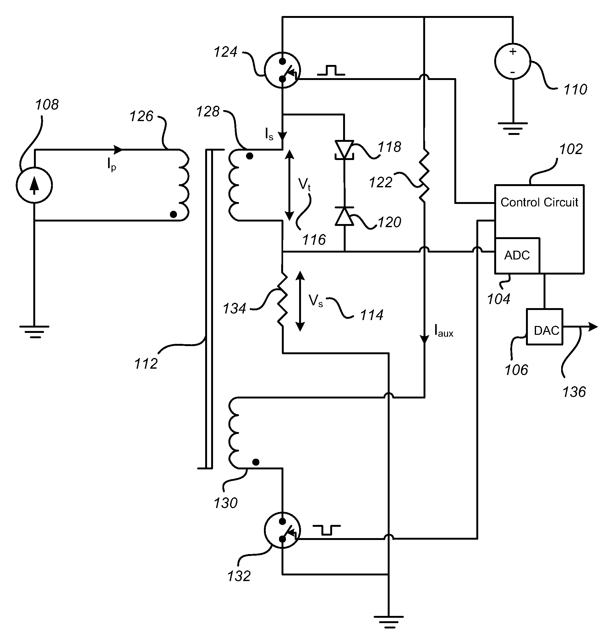
[0059]FIG. 6 represents a current sensor in accordance with the present invention. In this case, it is desired to measure a voltage or voltage difference rather than a current in accordance with the present invention. To do so, a resistor 404 is employed to convert the input voltage 402 into a current that flows through the primary winding 126. The voltage source, Vpot 406, is an arbitrary voltage, emphasizing that the sensor is able to measure a voltage difference or voltage 402 superimposed upon a high and changing voltage potential 406 by providing galvanic isolation. To keep power consumption low, the resistor 404 will generally be chosen to be quite large, thereby reducing the current flowing through the primary winding 126. To maintain the sensitivity of the sensing circuit, the number of turns in the primary winding 126 may be increased. The remainder of the circuit is identical to that shown in FIG. 3 with the exception of the optional digital-to-analog converter 106, which ...

fourth embodiment

[0060]FIG. 7 illustrates the current sensor in accordance with the present invention. In order to provide a low-cost analog output, a simple sample-and-hold circuit 504 is used to acquire the pulsed voltage appearing across resistor 134. The sample-and-hold circuit converts the pulsed voltage signal into a steady analog voltage output 506.

fifth embodiment

[0061]FIG. 8 illustrates a current sensor in accordance with the present invention. Here, the output circuit is configured to provide a digital output signal that changes state when the current being measured 108 exceeds a pre-set value. An analog comparator 606 is used to compare a reference voltage level 608 with the voltage 114 across the sense resistor 134. When the measured voltage 114 exceeds the reference voltage 608, the output of comparator 606 will change. Since the voltage 114 is available only during time t2, a D-Q flip flop is used to capture the state of the comparator at the sample time 320 (see FIG. 5).


PUM


Abstract

A current sensor is provided that employs a primary winding that carries the current to be measured, and a secondary winding that controls the flux inside the magnetic core, provides a sample of the primary current, and also helps to control the flux at small primary currents and to saturate the transformer. An auxiliary winding is optionally used to control the flux in order to simplify control of the sensor. By periodically applying a certain voltage at the secondary winding, the transformer core is forced out of saturation, and a sample of the primary current is taken by a sensing circuit that may include a sample-and-hold circuit and an analog-to-digital converter. A control circuit is employed to control the currents flowing in the secondary winding and optional auxiliary winding and to manage the sensing circuit.

Description

RELATED APPLICATION DATA[0001]This application claims the benefit, pursuant to 35 U.S.C. § 119(e), of U.S. provisional application Ser. No. 60 / 983,884, filed Oct. 30, 2007.BACKGROUND OF THE INVENTION[0002]1. Field of the Invention[0003]The present invention relates to devices for measuring electrical current by converting current into a voltage. More particularly, the invention relates to high-bandwidth devices for measuring both direct and alternating currents that are isolated from the circuit being measured.[0004]2. Description of Related and Prior Art[0005]Several techniques for measuring current are known. The simplest one comprises a shunt resistor inserted into the current path. While this method is inexpensive, it provides no isolation, and it consumes excessive power, especially when a large signal amplitude is required.[0006]Another technique employs a Hall-effect current sensor. This kind of sensor provides isolation, good resolution and low losses. Unfortunately, the ban...

Claims


Application Information

Patent Timeline
Patent Type & Authority Applications(United States)
IPC IPC(8): G01R15/18
CPCG01R15/185
Inventor ZIEGLER, SILVIO
Owner BEL POWER SOLUTIONS INC
Why Eureka
Try Eureka