Structures for enhanced detection of fluorescence

a fluorescence and structure technology, applied in the field of substrates, can solve the problems of time-consuming and costly manual methods, the structure employed to provide the observation platform fails to take full advantage of the characteristics of fluorescent probes, and the detection of these substrates is not taken into accoun

Active Publication Date: 2009-05-07
COMPLETE GENOMICS INC
View PDF15 Cites 29 Cited by
  • Summary
  • Abstract
  • Description
  • Claims
  • Application Information

AI Technical Summary

Benefits of technology

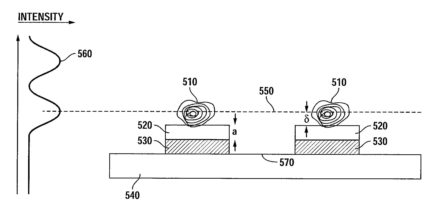
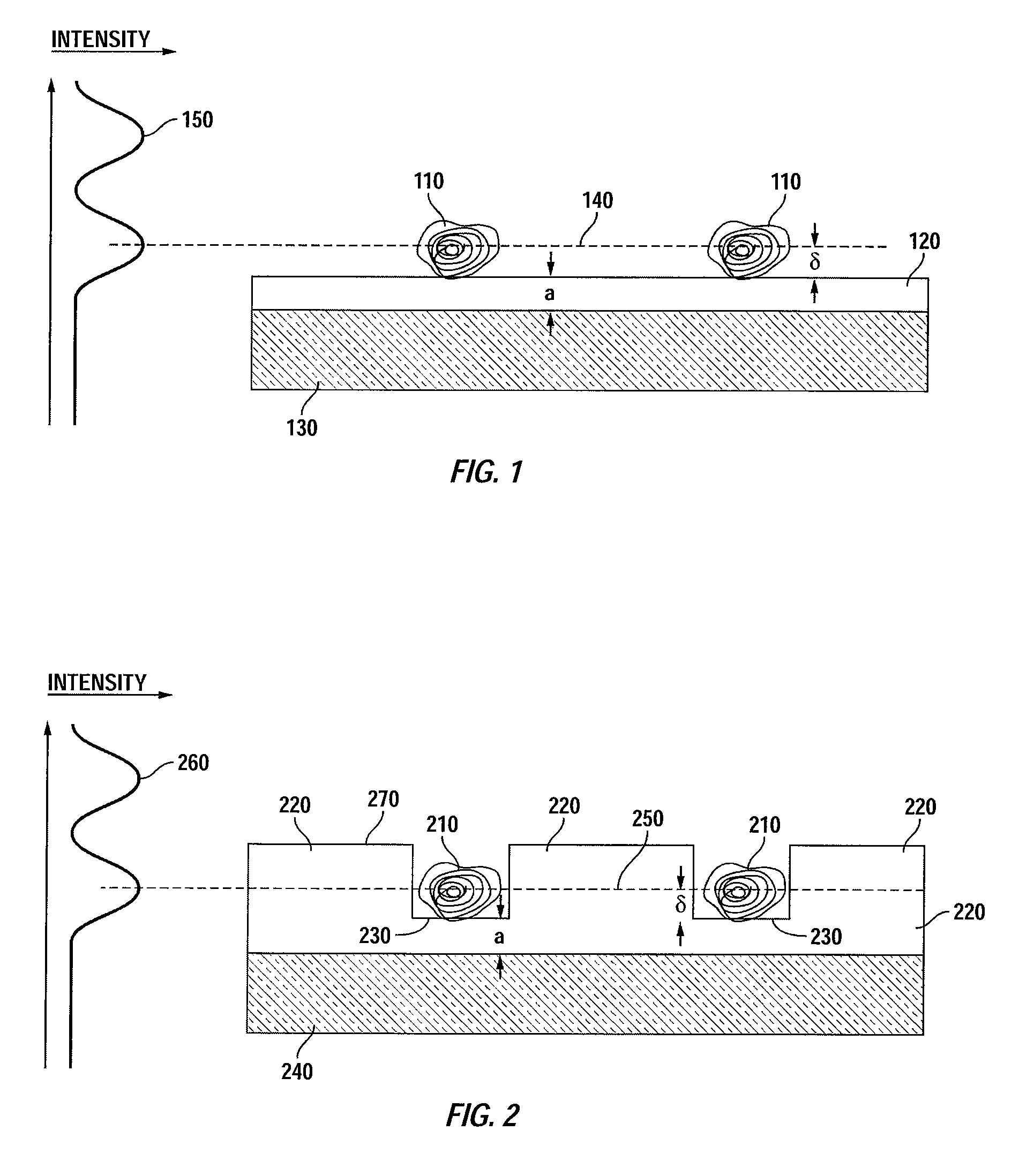
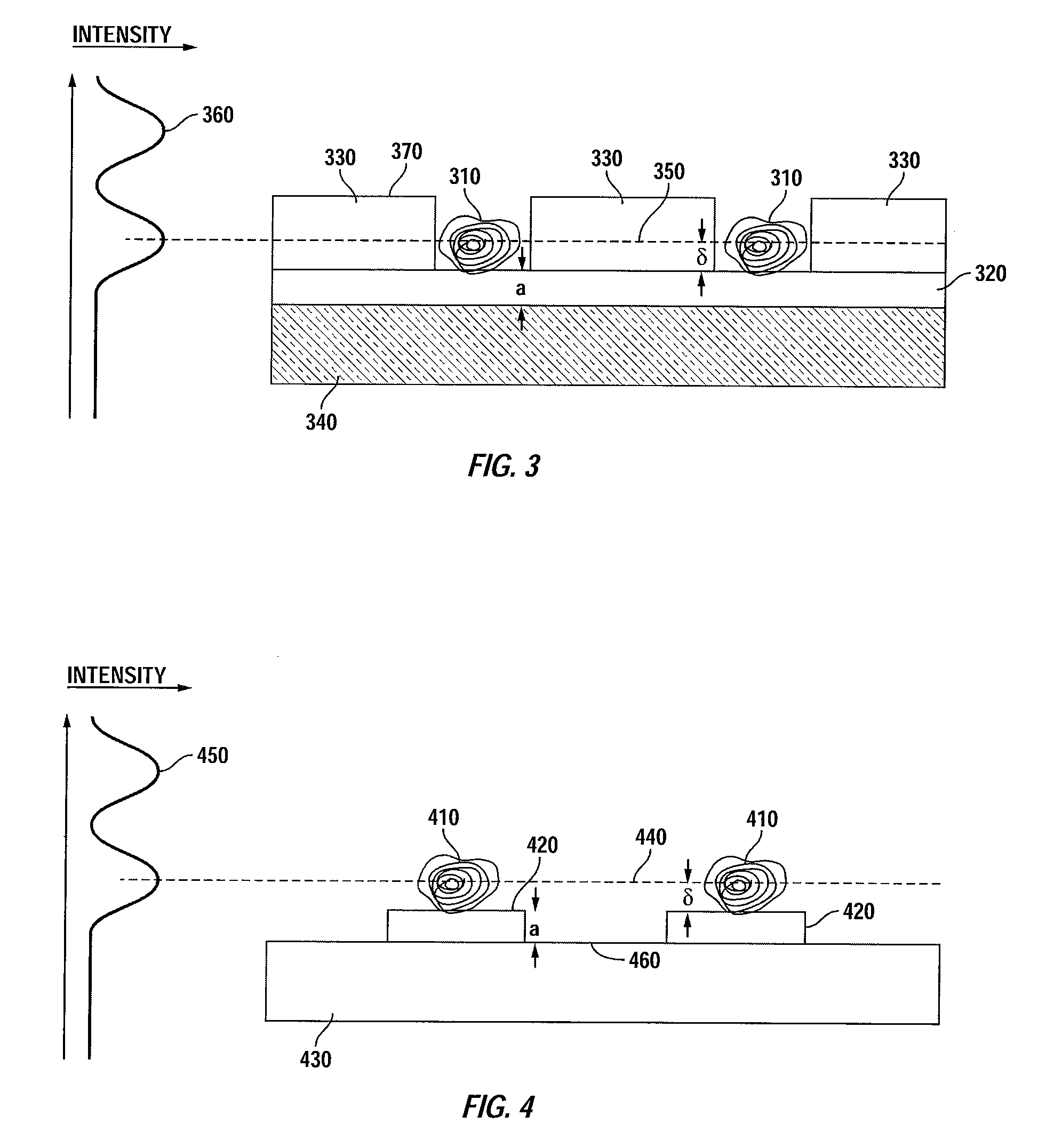
[0026]It is an advantage of the invention that the fluorescent enhancement layer can be constructed to have wells or raised areas in / on which the objects are positioned. This provides placement of the object to provide an intensity maximum for detection of the objects, while the surfaces between the objects are positioned at an intensity minimum.
[0027]It is another advantage of the invention that the fluorescent enhancement layer can be provided as a series of pedestals on the reflective substrate, upon which the object is positioned. This also provides placement of the objects to provide an intensity maximum for detection of the objects, while the surfaces between the objects are positioned at an intensity minimum.
[0028]In specific aspects of varying embodiments, the different introduced surface structures (e.g., depressions, raised areas, pedestals, etc.) are substantially the same to accommodate objects of the same or similar size and / or mass.
[0029]In other specific aspects, the depressions or the raised areas of the fluorescence enhancement layer on a single device may vary, e.g., structures in a single device may have a varying thickness. Such depressions or raised areas may be designed to accommodate objects of different sizes on a single device or to account for differences in the plane of maximum fluorescence when two or more fluorophores are being used. This allows for maximum detection of objects of varying size or multiple fluorophores using single excitation parameters.
[0030]It is a feature of the invention that it provides optimized detection of objects for which the plane of maximum fluorescence differs from the substrate surface.
[0031]It is a further feature of the invention that the substrate surface can be positioned at an intensity minimum, this decreasing background signal.

Problems solved by technology

The fluorescence of a sample has in the past been manually assessed by visual inspection through a conventional microscope, but this manual method is time-consuming and costly.
However, the structures employed to provide an observation platform fail to take full advantage of the characteristics of the fluorescent probes.
Sources of background noise include specular or diffuse reflection of the fluorescence-stimulating laser light from the sample, autofluorescence of the substrate holding the sample, autofluorescence from the optics in the light path of the optical imaging system, stray light, and dark current of the detector.
Detection using these substrates does not take into account the finite thickness of certain imaging samples, and thus are not optimized for samples in which the plane of maximum fluorescent signal differs from the surface.

Method used


Image

  • Structures for enhanced detection of fluorescence
  • Structures for enhanced detection of fluorescence
  • Structures for enhanced detection of fluorescence

Examples


example 1

Enhancing the Fluorescence Signal from a Labeled DNA: Concatamer Using a SiO2 / Si Substrate

[0070]The following example provides the calculation and construction of a sample substrate optimized to provide detection of fluorophores distributed through a plurality of DNA concatamers comprising approximately 1 Kb of nucleotides in a single-stranded, three dimensional construct attached to a SiO2 / Si substrate. The production of such concatamers is described, for example, in U.S. patent application Ser. No. 11 / 451,691, which is published Patent Application 2007 / 0099208 assigned to the assignee of the present invention.

[0071]For the present example, the finite average size of the DNA concatamers was factored into the calculation of the substrate construction to provide maximal detection of each DNA concatamer.

[0072]FIG. 9 displays a plot of the calculated total enhancement for a silicon substrate coated with a SiO2 layer as a function of the thickness of the oxide film, with a fluorophore-c...

example 2

Enhancing the Fluorescence Signal from a Labeled DNA: Concatamer Using a SiO2 / Al Substrate

[0074]The following example provides the calculation and construction of a sample substrate optimized to provide detection of fluorophores distributed through a plurality of DNA concatamers comprising approximately 1 Kb in a single-stranded, three dimensional construct attached to a SiO2 / Al substrate. For the present example, the finite average size of the DNA concatamers, 60 nm, was factored into the calculation of the substrate construction to provide maximal detection of each DNA concatamer.

[0075]Experimental data was obtained for a SiO2 / Al substrate having a plurality of DNA concatamers comprising multiple Cy3 fluorophores distributed throughout the molecule attached to the substrate surface. As seen in FIG. 11, the maximal fluorescent signal intensity as a function of oxide thickness for such concatamers attached to the surface occurs at a thickness of 45 nm, which was found empirically to...


PUM

PropertyMeasurementUnit
radiusaaaaaaaaaa
radiusaaaaaaaaaa
thicknessaaaaaaaaaa

Abstract

Substrates are provided for use in the detection, identification and analysis of biologic or chemical samples that are labeled with a fluorescent label, in which the plane of maximum fluorescence is displaced from a reflective substrate surface so that the intensity maximum of the standing wave interference pattern of incident and reflected probe radiation is enhanced. The format of the substrates includes substantially planar surfaces as well as substrates with introduced variations to the substrate surface, e.g., depressions, wells, pedestals and the like, disposed in arrays or other similar structures such that one or more fluorophore-comprising objects can be attached thereto.

Description

CROSS-REFERENCES TO RELATED APPLICATIONS[0001]The present application claims benefit under 35 USC 119(e) of U.S. provisional Application No. 60 / 984,652, filed on Nov. 1, 2007, entitled “Structures For Enhanced Detection Of Fluorescence,” the content of which is incorporated herein by reference in its entirety.STATEMENT AS TO RIGHTS TO INVENTIONS MADE UNDER FEDERALLY SPONSORED RESEARCH OR DEVELOPMENT[0002]NOT APPLICABLEREFERENCE TO A “SEQUENCE LISTING,” A TABLE, OR A COMPUTER PROGRAM LISTING APPENDIX SUBMITTED ON A COMPACT DISK.[0003]NOT APPLICABLEBACKGROUND OF THE INVENTION[0004]This invention relates to substrates for use in the fluorescent, phosphorescent or luminescent detection of biological or chemical samples. Fluorescence microscopy is often used in the fields of molecular biology, biochemistry and other life sciences for analyzing biological molecules, including nucleic acids (DNA, RNA) and proteins (enzymes, antigens, etc.) that have been tagged or labeled with fluorescent ...

Claims


Application Information

Patent Timeline
Patent Type & Authority Applications(United States)
IPC IPC(8): G01N21/64
CPCG01N21/6428G01N21/6452G01N2021/6441G01N2021/6421G01N2021/6419
Inventor FERNANDEZ, ANDRES
Owner COMPLETE GENOMICS INC
Why Eureka
Try Eureka