
Method and device for investigation of phase transformations in metals and alloys

a technology of phase transformation and metals, applied in the field of physical property measurement devices and devices for investigating phase/state changes, instruments, heat measurement, etc., can solve the problems of affecting the heating and cooling rate of the investigated specimen, affecting the application of traditional dta techniques using sophisticated and expensive devices, and achieving the effect of reliable, fast and inexpensive monitoring, and potential for determining weld solidification cracking susceptibility

Active Publication Date: 2009-05-07
THE OHIO STATES UNIV
View PDF33 Cites 5 Cited by
  • Summary
  • Abstract
  • Description
  • Claims
  • Application Information

AI Technical Summary

Benefits of technology

SSDTA provides accurate and cost-effective monitoring of phase transformations, enabling the determination of optimal welding conditions and material properties, with higher sensitivity than traditional methods and applicability to various thermal and thermo-mechanical processes.

Problems solved by technology

The heat consumption or release that accompany the phase transformations impact the heating and cooling rates of the investigated specimen.
The traditional DTA technique utilizes sophisticated and expensive devices that operate in a short range of heating and cooling rates of up to about twenty degrees Celsius per minute.
Such limitation makes this approach inapplicable for investigating the phase transformation in materials where actual processing conditions must be simulated.
This approach is limited in depicting the actual heating and cooling rates and thermal gradients, and utilizes expensive, specialized equipment.
Such an approach is not applicable for investigating solidification and solid-state phase transformations in the weld metal and therefore is not useful for constructing weld metal CCT diagrams.
DTA methods and devices were also used for constructing CCT diagrams; however, because of the maximum heating and cooling rates for these techniques are so low, they are generally inappropriate for constructing a useful CCT diagram.
Disadvantages of such a method include the amplification of electromagnetic noise, recorded over the thermal cycle, the low sensitivity to and difficult recognition of higher temperature phase transformations, and low accuracy of determining phase transformation starting and finishing temperatures.
In addition, the experiment is difficult to control.
The manner of obtaining the reference thermal cycle limits the applicability of this approach only to solid-state phase transformations in the HAZ and does not allow investigating the solidification behavior and the other phase transformations in weld metal.
Since DA has low sensitivity to some solid-state phase transformations, it is inapplicable for solid-liquid phase transformations, and is insensitive to most structural changes.
Nevertheless, DA cannot be used in-situ, as it requires special sample types and can only detect phase transformations where there is a significant change in sample dimension.
In addition, it cannot detect structural changes, such as recrystallization.
Because of the control loops used for controlling the heating and cooling rates, DTA is inapplicable in combination with such devices.
Some thermo-mechanical simulators are not capable of reproducing the extremely high heating and cooling rates at the high temperature range that are typical for the most welding processes.
The above technique is not capable of simulating the solid-liquid and solid-state phase transformations.
In addition, the simulation equipment is complex in shape and involves expensive laboratory setups.
The main disadvantages of this equipment are that it has difficulty in resembling the actual weld and HAZ heating and cooling rates.
In addition, it exhibits non-uniform heating of the HAZ simulation specimen.
Moreover, the small volume of the weld simulation specimen does not allow resembling the actual weld solidification patterns.
The available methods and devices have a number of disadvantages that limit their usefulness for measuring phase transformations and structural changes in structural alloys during actual or simulated processing.

Method used


Image

  • Method and device for investigation of phase transformations in metals and alloys
  • Method and device for investigation of phase transformations in metals and alloys
  • Method and device for investigation of phase transformations in metals and alloys

Examples


Embodiment Construction

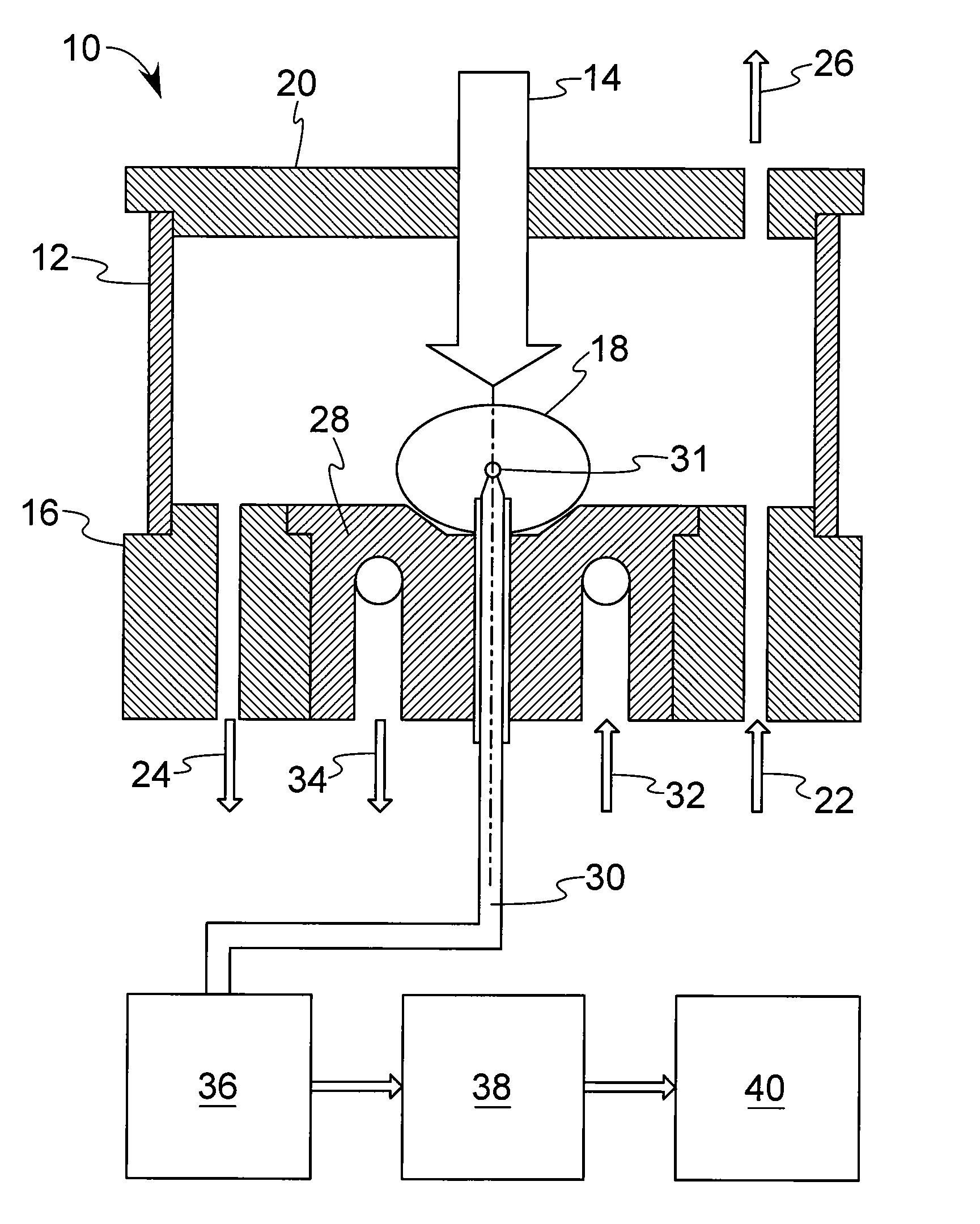
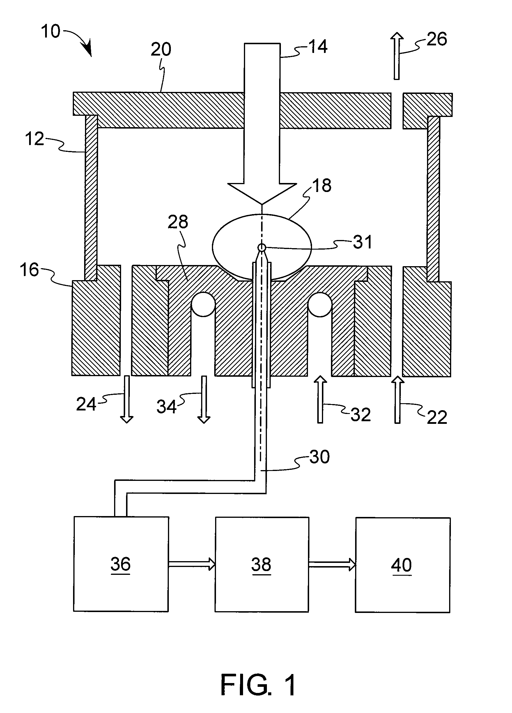
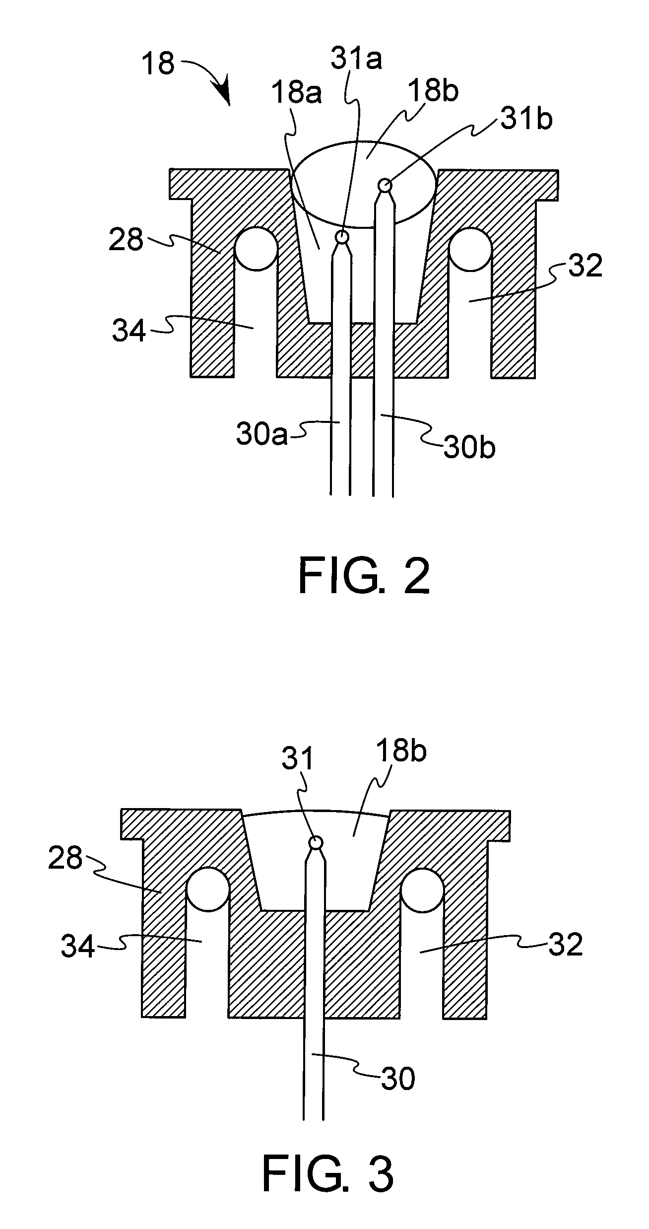
[0042]Referring first to FIGS. 1 through 3, an embodiment of the device 10 according to the present invention includes a chamber 12, a source of energy 14, and a hearth 16 (shown with particularity as 16A) on which a specimen of material 18 is heated. Specimens 18 can exist in a solid state (i.e., not melted), solid-liquid state (i.e., partially melted) or liquid state (i.e., completely melted). The chamber 12 is made of a heat-resistant material (such as metals and their alloys), and forms a hermetic seal between the hearth 16 and a lid 20. In certain forms, the heat-resistant chamber material may be transparent, such as the aforementioned borosilicate glass. In one form, the chamber 12 forms a hermetic seal between the hearth 16 and lid 20. A controlled atmosphere is maintained in the chamber 12 to protect the specimen 18 from the surroundings, and may include an inlet 22 and outlet 24. In addition, a vacuum 26 can be used to help maintain the controlled atmosphere. The specimen 1...


PUM


Abstract

A device and method for investigating phase transformation properties and structural changes of materials. In one form, the device simulates actual thermal processing conditions, while the method can be used in both simulations as well as in actual processing conditions. An analysis using at least one of the device and method is referred to as a single sensor differential thermal analysis, as it compares the temperature recorded in a measured specimen against a reference thermal history without requiring the derivation of the reference thermal history from measured reference temperatures.

Description

CROSS-REFERENCE TO RELATED APPLICATION[0001]This application is a divisional of co-pending (and now-allowed) application Ser. No. 11 / 410,277, filed Apr. 24, 2006. This application claims the benefit of the filing date of U.S. Provisional Application No. 60 / 673,879, filed Apr. 22, 2005.STATEMENT REGARDING FEDERALLY SPONSORED RESEARCH OR DEVELOPMENT[0002]This invention was supported by the government under Contract No. DGE-0312160 awarded by the National Science Foundation (NSF). The government has certain rights in the invention.BACKGROUND OF THE INVENTION[0003]The present invention generally relates to a device and method for measuring the physical property of a material as a function of that material's temperature, and more particularly to a device and method for measurement of solid-liquid and solid-state phase transformations and structural changes in materials under simulated and actual conditions associated with thermal and thermo-mechanical processing of such materials.[0004]T...

Claims


Application Information

Patent Timeline
Patent Type & Authority Applications(United States)
IPC IPC(8): G01N25/02G01N25/00
CPCG01N25/4866G01N25/04
Inventor ALEXANDROV, BOIAN TODOROVLIPPOLD, JOHN C.NORTON, SETH JASON
Owner THE OHIO STATES UNIV
Learn More