Method and system for estimating in-cylinder pressure and knocking utilizing an in-cylinder pressure sensor

a pressure sensor and in-cylinder technology, applied in the field of pressure sensors, can solve the problems of limited lifetime, unacceptably expensive, and electromagnetic interference, and achieve the effect of reducing the cost of piezoceramic devices such as spark plug washers and boss-type sensors, and not offering high accuracy under all engine conditions

Inactive Publication Date: 2009-05-14
HONEYWELL INT INC
View PDF18 Cites 24 Cited by
  • Summary
  • Abstract
  • Description
  • Claims
  • Application Information

AI Technical Summary

Benefits of technology

[0012]It is another aspect of the present invention to provide for improved methods and systems for the accurate estimation of in-cylinder parameters such as, for example, pressure and knocking.

Problems solved by technology

They are subject to electromagnetic interference (EMI) effects, have limited lifetime, and are unacceptably expensive.
Similarly lower cost piezoceramic devices, such as spark plug washers and boss-type sensors, do not offer high accuracy under all engine conditions, are subject to electrical interference problems, and are prone to large temperature errors.
The degrading effect of alloy segregation, selective oxidation, and diffusion reduces the durability of these sensors and is not sufficient for use in production engines.
Similarly, these sensors have limitation in working continuously at very high temperature of about 1000° C.
The ion current measurement to measure the ionization needs a high voltage source and it is quite complicated and expensive.

Method used


Image

  • Method and system for estimating in-cylinder pressure and knocking utilizing an in-cylinder pressure sensor
  • Method and system for estimating in-cylinder pressure and knocking utilizing an in-cylinder pressure sensor
  • Method and system for estimating in-cylinder pressure and knocking utilizing an in-cylinder pressure sensor

Examples


Embodiment Construction

[0028]The particular values and configurations discussed in these non-limiting examples can be varied and are cited merely to illustrate at least one embodiment and are not intended to limit the scope thereof.

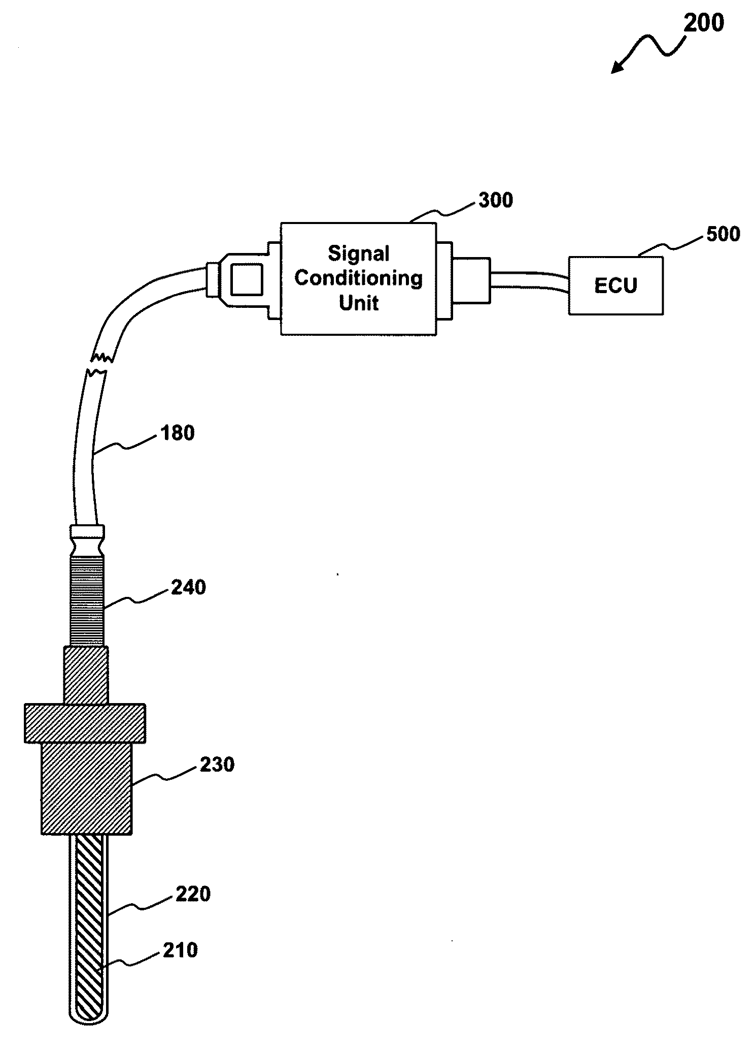
[0029]Referring to FIG. 3 a block diagram representation 50 of an in-cylinder pressure sensor 200 and a data acquisition system 400 for analyzing and estimating in-cylinder parameters is illustrated, in accordance with a preferred embodiment. The in-cylinder pressure sensor 200 can be mounted on an engine cylinder 100 and the output from the sensor 200 can be electrically connected to a signal conditioning unit 300. A data acquisition system 400 receives signals from the signal-conditioning unit 300 and processes the signals in accordance with engine combustion pressure using image charge sensing principles. The signal conditioning unit 300 includes a charge amplifier 310 and a differential amplifier 320. The differential amplifier 320 subtracts the signals from the charge ampl...


PUM

PropertyMeasurementUnit
temperatureaaaaaaaaaa
voltageaaaaaaaaaa
voltageaaaaaaaaaa

Abstract

A system for measuring in-cylinder parameters utilizing an image charge measured in an engine cylinder by an in-cylinder pressure sensor due to chemi and or thermal ionization in Engine. The in-cylinder pressure sensor includes a sensing element, which is a metal sensor probe with a selective coating (e.g., metal, oxides of metal, native oxides, semiconductor, oxides of semiconductors, ceramics, glass, dielectric, etc., in the form of a coating on the metallic probe, tube, etc) in order to function in harsh, corrosive and/or elevated temperature environments. The output of the sensor can be connected to a signal-conditioning unit, which includes a low noise differential charge amplifier with an auto offset correction circuit to measure fast varying signals. The signal out from the conditioning unit can be acquired utilizing a high-speed microcontroller-based data acquisition system with suitable software to analyze and estimate parameters such as, for example, in cylinder pressure and knocking.

Description

TECHNICAL FIELD[0001]Embodiments are generally related to pressure sensors. Embodiments are also related to in-cylinder pressures sensors. Embodiments are additionally related to a methods and systems for estimating in-cylinder pressure and engine knocking.BACKGROUND OF THE INVENTION[0002]Increasing emission standards demands for reduced hazardous exhaust gas emissions and improved fuel economy for automobile engines. Engine performance and its emission generally depend on various parameters, such as, for example, air-fuel ratio, engine pressure, combustion temperature, EGR (Exhaust Gas Recirculation) circulation and ignition timing. Vehicles can include an internal combustion engine that generates drive torque to drive wheels. More specifically, the engine draws in air and mixes the air with fuel to form combustion mixture. The combustion mixture is compressed within cylinders so that the mixture gets combusted in order to drive pistons that are slidably disposed within respective ...

Claims


Application Information

Patent Timeline
Patent Type & Authority Applications(United States)
IPC IPC(8): G01L23/22G01M15/08
CPCG01L23/221G01M15/08G01L23/225
Inventor ANILKUMAR, RAMSESHK.P., BABURAJTHANIGACHALAM, PALANI
Owner HONEYWELL INT INC
Why Eureka
Try Eureka