

Ultra high pressure machining spindle
a high-pressure machining and spindle technology, applied in the direction of driving apparatus, attachable milling devices, manufacturing tools, etc., can solve the problems of limiting the metal removal rate and therefore affecting the speed and power capacity of the spindle, and affecting the productivity of the spindle system. , the damage to the spindle is more sever
- Summary
- Abstract
- Description
- Claims
- Application Information
AI Technical Summary
Benefits of technology
Problems solved by technology
Method used
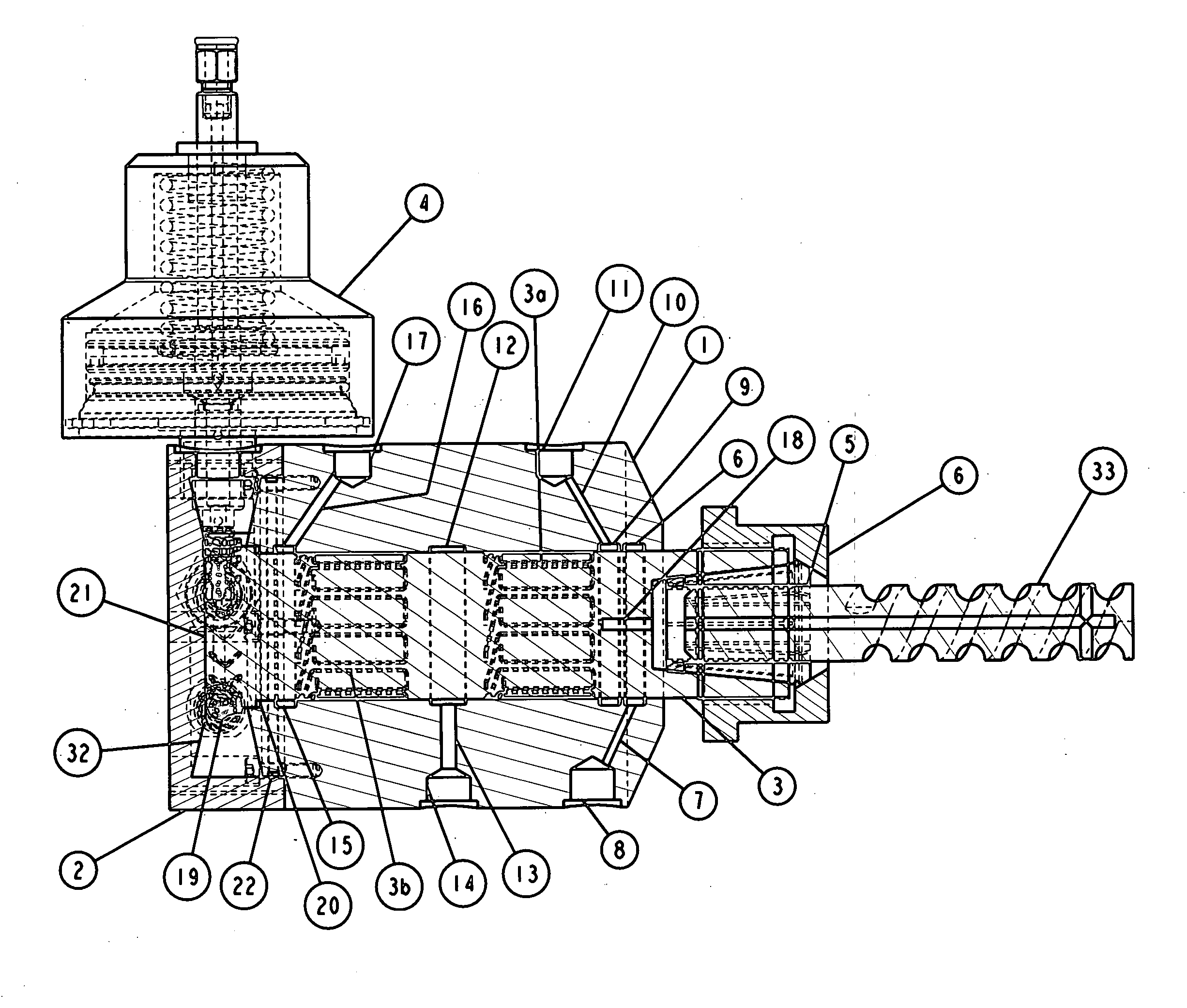
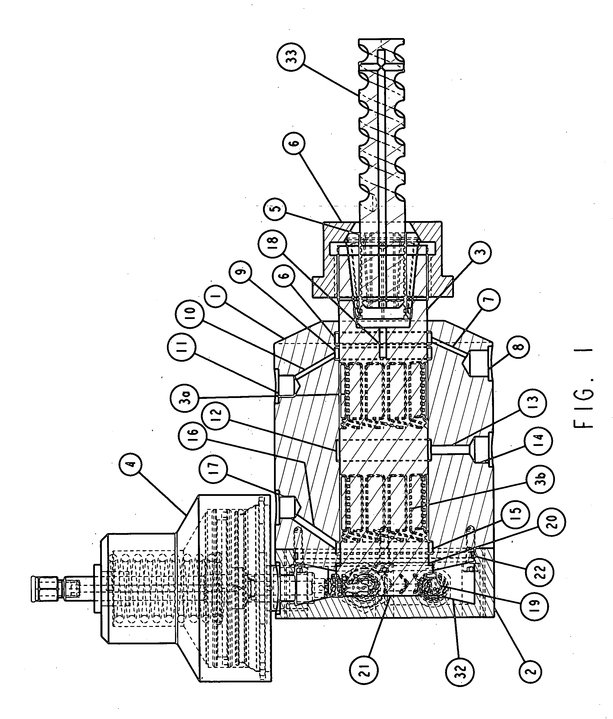
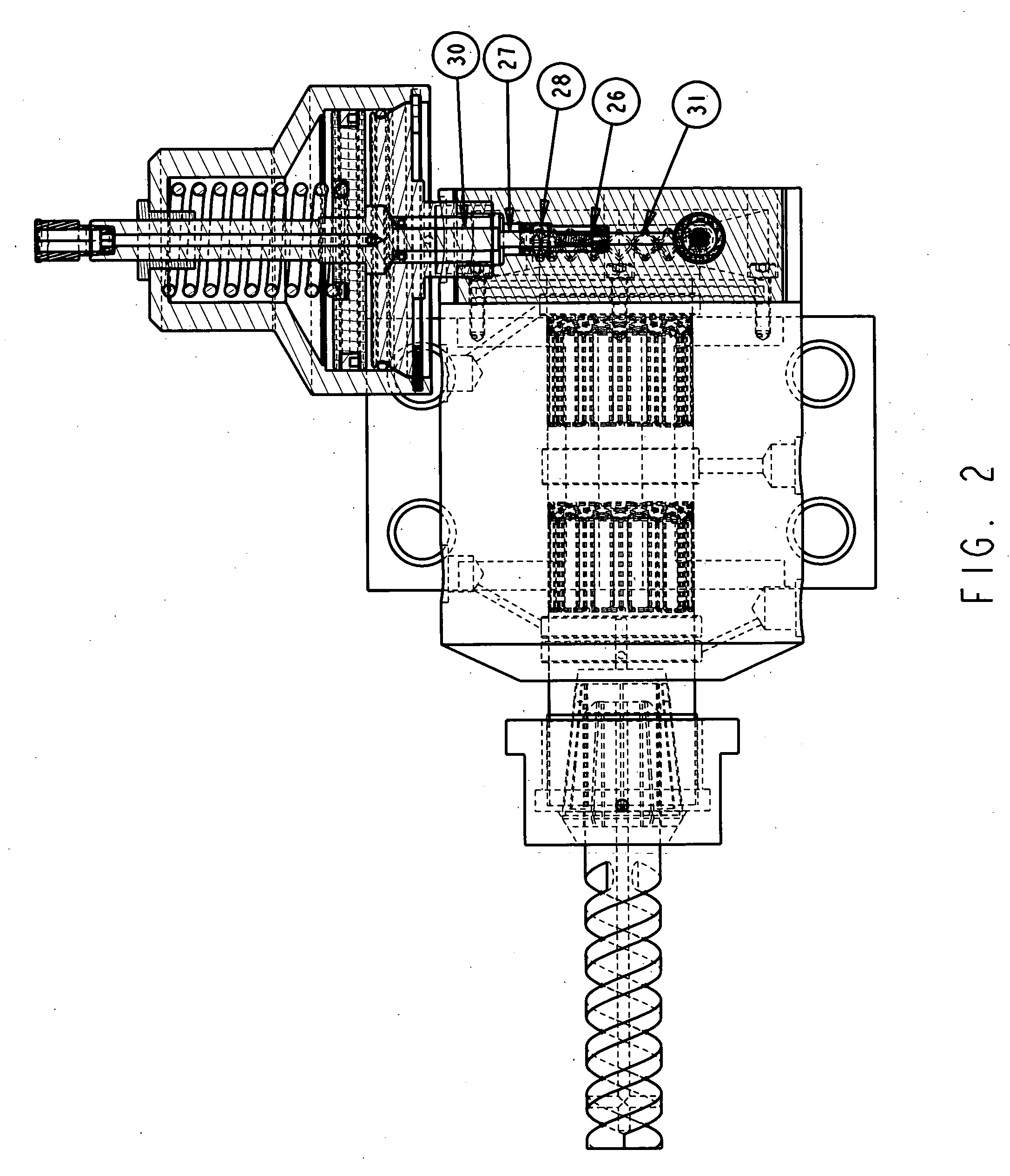
Image

Examples
Embodiment Construction
[0020]In order for developed societies to compete in manufacturing they must have more advanced tool that can enable their higher paid machinists the ability to produce parts faster than lower paid machinists. This can be accomplished in many ways using automation. It is noted that the cost of automation can offset the increase in productivity. A better approach would be to increase the metal removal rate and thereby reduce the time to produce the same part. This is especially true when cutting parts that require a long time on the machine such as aircraft parts or the like, the answer is a several order of magnitude increase in the metal removal rates. This results from the use of higher spindle speeds which provide this performance increase over that of conventional machines. (This is generally what lower cost producers generally have available to them.)
[0021]The critical goal, therefore, for manufacturers is to be able to obtain very high speed for tools, using an economical and ...
PUM
| Property | Measurement | Unit |
|---|---|---|
| Force | aaaaa | aaaaa |
| Pressure | aaaaa | aaaaa |
| Speed | aaaaa | aaaaa |
Abstract
Description
Claims
Application Information