Variable Capacitance Circuit

a capacitance circuit and variable technology, applied in variable capacitors, line-transmission details, multiple-port networks, etc., can solve the problems of high loss at a high frequency, circuit loss can be lower, distortion including waveform distortion and intermodulation distortion is large, etc., to reduce distortion, reduce current consumption, and high power handling capability

Active Publication Date: 2009-05-21
KYOCERA CORP
View PDF9 Cites 23 Cited by
  • Summary
  • Abstract
  • Description
  • Claims
  • Application Information

AI Technical Summary

Benefits of technology

[0012]The invention has been devised in view of the problems of conventional art as described above, and its object is to provide a variable capacitance circuit which satisfies both of

Problems solved by technology

However, the circuit employing the variable capacitance diode is allowed to be used only in a receiver or receiving circuit adapted for low power because the variable capacitance diode is low in power handling capability and experiences large distortion due to capacitance nonlinearity, that is, the circuit has problems of being not allowed to be used in a transmitter or transmitting circuit adapted for high power and furthermore of having a high loss at a high frequency.
In the circuit employing the variable capacitance element having the thin-film dielectric layer with dielectric constant varying with a direct-current voltage, the circuit loss can be lower because the loss in the variable capacitance element can be lower even at a high frequency, but the variable capacitance element has its capacitance varying even with a high frequency voltage and therefore has such a problem that distortion including waveform distortion and intermodulation distortion is larger in the case where the high frequency voltage is high.
In order to reduce the above distortion, high-frequency field strength of the variable capacitance element needs to be lowered to reduce the capacitance variation caused by the high frequency voltage, and to achieve this, it is effective to increase a thickness of the dielectric layer, but the increase in thickness of the dielectric layer reduces direct-current field strength, which causes problems of decreases in a rate of capacitance change and in a control width of the impedance, resonant frequency, or the like, of the circuit.
With a high frequency signal, the variable capacitance element carries an electric current more easily and therefore, in the case of using the variable capacitance element in the variable capacitance circuit, loss resistance may cause the variable capacitance element to generate heat and be broken during use, which causes a pro

Method used


Image

  • Variable Capacitance Circuit
  • Variable Capacitance Circuit
  • Variable Capacitance Circuit

Examples


specific examples

[0055]A method of calculating the number of variable capacitance elements (the number of variable capacitance capacitors) in the second variable capacitance element unit will be specifically described hereinbelow, but such a calculating method is not limited to the following examples.

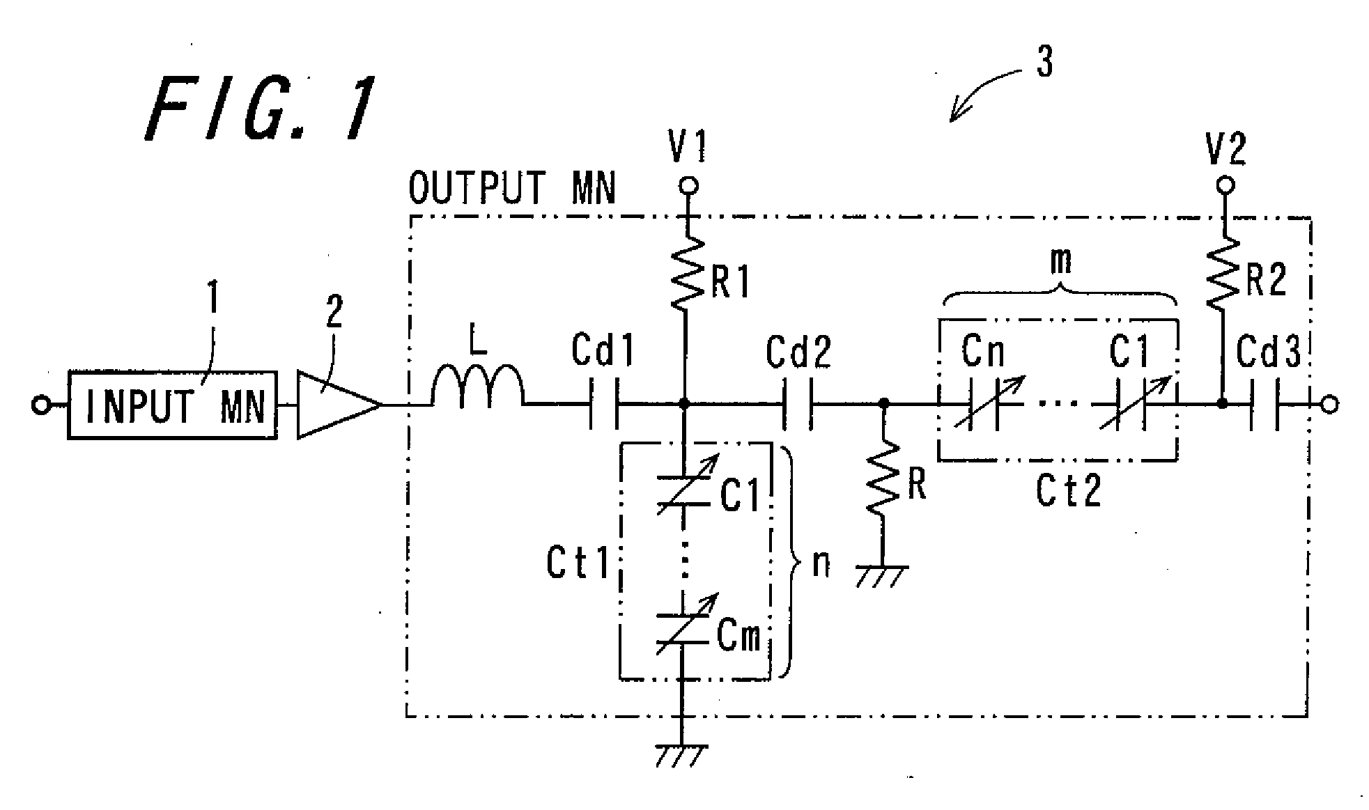
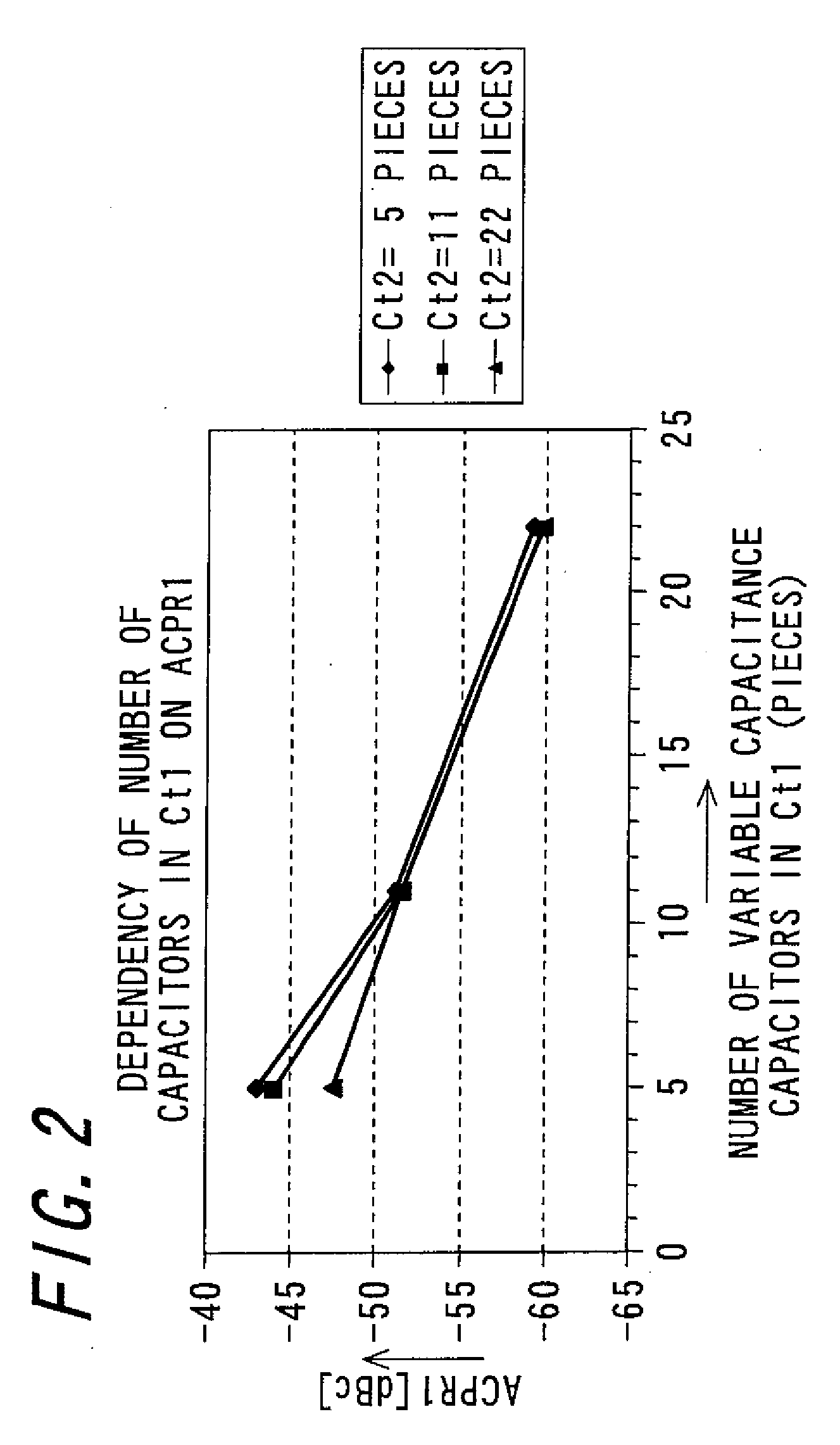
[0056]In the calculation, distortion of an output watching network of a variable capacitance circuit (in this case, an adjacent channel power ratio (ACPR1) acting as one of indicators for distortion characteristics) is calculated, followed by calculating in a circuit simulator the dependency of the number of capacitors in the first variable capacitance element unit Ct1 as well as the dependency at the number of capacitors in the second variable capacitance element unit Ct2, on the ACPR1.

[0057]The high frequency voltage inputted to the first variable capacitance element unit Ct1 and the second variable capacitance element unit Ct2 shown in FIG. 1 varies depending on the circuit constant being used or the...


PUM


Abstract

The invention relates to a variable capacitance circuit which achieves reduction in both of distortion and current consumption and furthermore achieves requirements of high power handling capability, cost reduction, and downsizing of the circuit. The variable capacitance circuit includes a first variable capacitance element unit having n pieces (where n is a natural number of two or more) of variable capacitance capacitor connected in series with respect to high frequency and in parallel with respect to direct current, each of the variable capacitance capacitors including one or more variable capacitance elements, each of which includes a dielectric layer with dielectric constant varying according to an applied direct-current voltage and a pair of electrodes sandwiching the dielectric layer therebetween, and a second variable capacitance element unit which has an applied voltage amplitude smaller than a voltage amplitude of high frequency signal applied to the first variable capacitance element unit, the second variable capacitance element unit including one piece of the variable capacitance elements or having m pieces (where m is a natural number smaller than n) of the variable capacitance elements connected.

Description

TECHNICAL FIELD[0001]The invention relates to a variable capacitance circuit having a variable capacitance element which has a dielectric body of which dielectric constant is varied by application of a direct-current voltage, and impedance, resonant frequency or the like are varied by variation of capacity, whereby circuit characteristics can be made variable, which variable capacitance circuit is used in a wireless communication device such as a mobile phone, and relates in particular to the variable capacitance circuit which has excellent characteristics such as small distortion and low current consumption.BACKGROUND ART[0002]There has been a conventionally-known circuit which incorporates an impedance element such as a capacitor, a resistance, an inductor, and a transmission line, with a variable capacitance diode, to change impedance, resonant frequency or the like and thereby provide desired circuit characteristics, thus allowing for switching of frequency bands and decreasing ...

Claims


Application Information

Patent Timeline
IPC IPC(8): H04B3/04H01G7/00H03H7/20
CPCH01G7/06H03H7/38H03H7/20
Inventor KATTA, HIROSHI
Owner KYOCERA CORP
Why Eureka
Try Eureka