Controlled and selective formation of catalyst nanaoparticles

a technology of catalyst nanoparticles and nanoparticles, which is applied in the field of catalyst nanoparticles, can solve the problems of incompatibility of current growth parameters, inability to synthesize different cnts with identical properties, and inability to fully realize similar applications

Inactive Publication Date: 2009-05-21
INTERUNIVERSITAIR MICRO ELECTRONICS CENT (IMEC VZW)
View PDF3 Cites 20 Cited by
  • Summary
  • Abstract
  • Description
  • Claims
  • Application Information

AI Technical Summary

Benefits of technology

[0077]By using this method, locations where recesses have to be formed can very accurately be determined.
[0078]According to preferred embodiments, the substrate may comprise a base substrate. Forming recesses in the substrate at predetermined locations may be performed by forming recesses in the base substrate. This may be advantageous when used in the manufacturing of e.g. semiconductor devices where a contact is required between the elongate nanostructures which may be grown on the substrate using the nanoparticles as a cata

Problems solved by technology

These and similar applications cannot be fully accomplished yet since the fabrication of any CNT-based device still faces a variety of unsolved issues, which vary from one application to another but may, however, be similar in some respects.
A first issue is related to the impossibility of synthesizing different CNTs with identical properties.
A second issue is the incompatibility of the current growth parameters with realistic batch-type technology integration schemes.
A fin

Method used


Image

  • Controlled and selective formation of catalyst nanaoparticles
  • Controlled and selective formation of catalyst nanaoparticles
  • Controlled and selective formation of catalyst nanaoparticles

Examples


example 1

Formation of Metal Nanoparticles

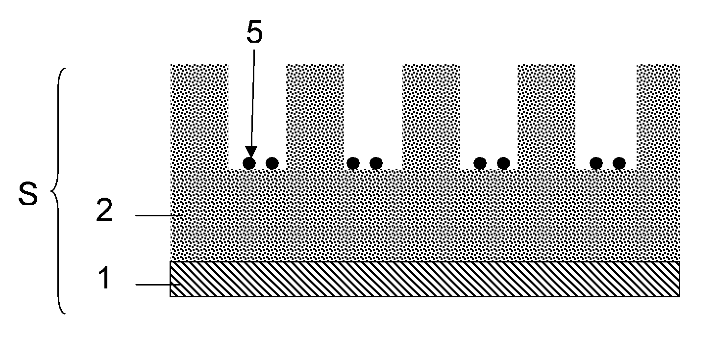
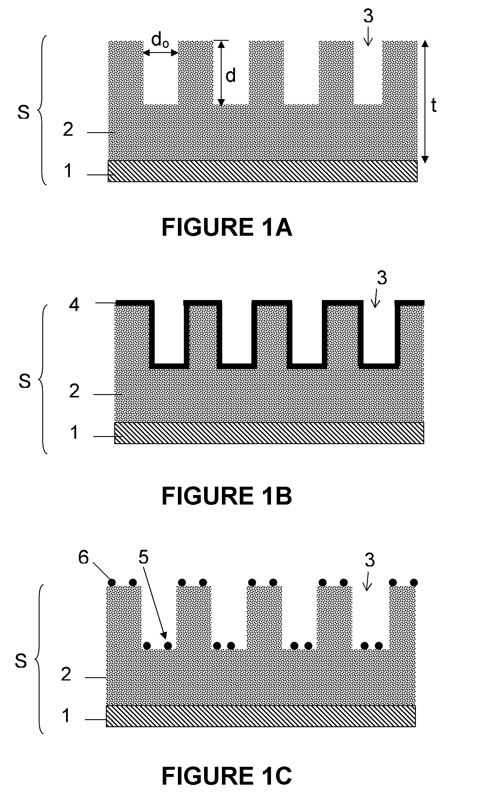
[0152]Pure metal nanoparticles 5, 6 resulting from an 8 nm and 2 nm thick layers of Ni and Co are evaluated.

[0153]A Ni layer 4 was deposited using Physical Vapor Deposition (PVD) and the layer 4 was annealed at a temperature of 700° C. for 1 minute. The nanoparticle size distribution was determined by SEM characterization. Under the mentioned annealing conditions, the particle diameter of the nanoparticles 5, 6 originating from the 8 nm thick deposited Ni layer was 67 nm±6 nm. The particle diameter of the nanoparticles 5, 6 originating from the 2 nm thick deposited Ni layer was 17 nm±4 nm.

[0154]Pure metal nanoparticles 5, 6 resulting from an 8 nm and 2 nm thick Co layer show exactly the same behavior as observed for Ni layers with the same thickness.

[0155]It can thus be concluded that the diameter of the nanoparticles 5, 6 depends on the thickness of the layer 4 of catalyst material, in the example given the thickness of the metal, i.e. Ni or Co, laye...

example 2

Growth of CNTs Using Co and Ni Nanoparticles as a Catalyst

[0156]In order to fully evaluate the catalytic activity of the Ni and Co (pure metal) nanoparticles 5 after the entire process of selectively obtaining nanoparticles 5 according to preferred embodiments, the Ni and Co nanoparticles 5 were exposed to a wide range of synthesis conditions. A CVD chamber was used for performing CNT growth. The system may comprise a load-lock pre-chamber from which samples can be transferred, using a magnetic transfer rod, to a fixed bed reactor comprising an 80 mm diameter quartz tube, 120 cm in length and surrounded by a horizontal furnace. The pressure of the system can be varied from atmospheric pressure to 1 mbar, whereas the temperature can reach 1200° C. A carbon source, hydrogen and nitrogen gases are supplied directly to the fixed bed reactor at flow rates ranging from 100 to 5000 ml / min and a maximum pressure of 3 bar. All samples were preconditioned at the desired growth temperature. Ea...

example 3

Evaluation of Growth Parameters in CVD Grown CNT

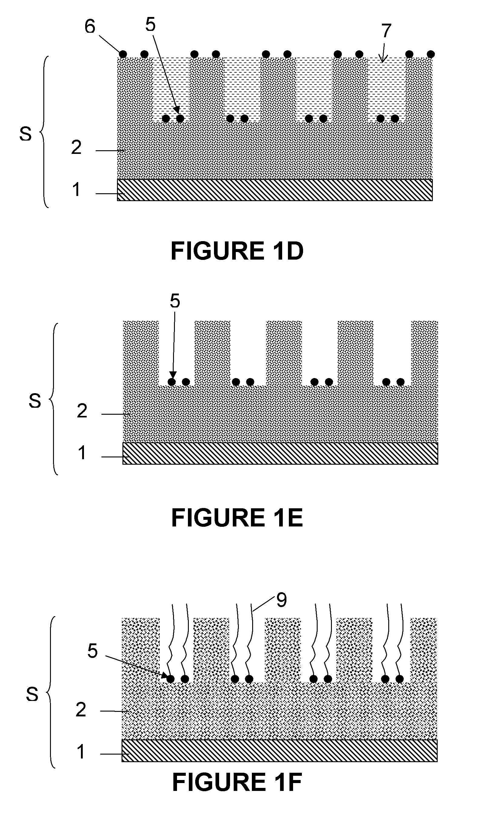
[0163]For a further evaluation of growth parameters as described in example 2, the time period of growth and the carbon source flow rate were reduced to respectively 30 seconds and 10 ml / min, while the growth temperature was increased to 900° C. An immediate effect on the growth of the CNTs 9 was observed. This is illustrated in FIG. 5C. Single CNTs 9 were grown from only some of the recesses 3, not from all of the recesses 3. Due to the limited amount of carbon source and reduced growth time, CNT length was controlled. In addition, an effect on the morphology was clearly observed. All CNTs 9 were straight. On the other hand, not all the nanoparticles appeared to be active under these circumstances. This is probably due to a poisoning effect at high temperature, as already described above.


PUM

PropertyMeasurementUnit
Temperatureaaaaaaaaaa
Evaporation enthalpyaaaaaaaaaa

Abstract

A method for forming catalyst nanoparticles on a substrate and a method for forming elongate nanostructures on a substrate using the nanoparticles as a catalyst are provided. The methods may advantageously be used in, for example, semiconductor processing. The methods are scalable and fully compatible with existing semiconductor processing technology. Furthermore, the methods allow forming catalyst particles and elongate nanostructures at predetermined locations on a substrate.

Description

CROSS-REFERENCE TO RELATED APPLICATIONS[0001]This application claims the benefit under 35 U.S.C. § 119(e) of U.S. provisional application Ser. No. 60 / 876,234, filed Dec. 21, 2006, and claims the benefit under 35 U.S.C. § 119(a)-(d) of European application No. 07006228.6, filed Mar. 3, 2007, the disclosures of which are hereby expressly incorporated by reference in their entirety and are hereby expressly made a portion of this application.FIELD OF THE INVENTION[0002]The preferred embodiments relate to catalyst nanoparticles. More particularly, a method for forming catalyst nanoparticles on a substrate is provided. Furthermore, a method for forming elongate nanostructures on a substrate using the catalyst nanoparticles formed by a method according to preferred embodiments is provided. The methods according to the preferred embodiments can be used with any size of substrate and are fully compatible with existing semiconductor processing, e.g. for manufacturing nano-devices.BACKGROUND O...

Claims


Application Information

Patent Timeline
IPC IPC(8): B01J23/00D01F9/12H01L21/04B82B1/00B82B3/00
CPCB01J23/75B01J23/755B01J35/0013B01J35/006B01J37/08B82Y30/00B82Y40/00H01L2924/0002C01B31/0233H01L21/76879H01L23/53276H01L2221/1094H01L2924/00C01B32/162
Inventor ESCONJAUREGUI, SANTIAGO CRUZWHELAN, CAROLINE
Owner INTERUNIVERSITAIR MICRO ELECTRONICS CENT (IMEC VZW)
Why Eureka
Try Eureka