Side Impact Sensor Systems

a sensor system and side impact technology, applied in the registration/indication of the working of vehicles, vehicle seats, special data processing applications, etc., can solve the problems of not being widely adopted partially, self-contained airbag systems have only achieved limited acceptance of frontal impacts, etc., and achieve the effect of reducing the size, weight and cost of the system

Inactive Publication Date: 2009-05-21
AMERICAN VEHICULAR SCI
View PDF53 Cites 12 Cited by
  • Summary
  • Abstract
  • Description
  • Claims
  • Application Information

AI Technical Summary

Benefits of technology

[0016]Problems resulting from the hole in the inflator wall when a percussion primer is used as in Breed, U.S. Pat. No. 4,711,466, are solved in the present invention through the placement of sensitive pyrotechnic material in a cavity adjacent to the outside wall of the inflator and then using shock from a stab primer to initiate the pyrotechnic material and thus the inflator. An alternate solution, as discussed below, is to make the size of the hole created in the inflator by the action of the stab primer small so that the total q

Problems solved by technology

In spite of these advantages, self-contained airbag systems have only achieved limited acceptance for frontal impacts and have so far not been considered for side impacts.
The “all-mechanical” self-contained systems were the first to appear on the market for frontal impacts but have not been widely adopted partially due to their sensitivity to accelerations in the vertical and lateral directions.
These cross-axis accelerations have been shown to seriously degrade the performance of the most common all mechanical design that is disclosed in Thuen, U.S. Pat. No. 4,580,810.
Both frontal and side impact crashes frequently have severe cross-axis accelerations.
Additionally, all-mechanical self contained airbag systems, such as disclosed in the Thuen patent, require that the sensor be placed inside of the inflator which increases the strength requirements of the inflator walls and thus increases the size and weight of the system.
One disadvantage of this system is that a hole must still be placed in the inflator wall to accommodate the percussion primer that has its own housing.
Another disadvantage in the Thuen system that makes it unusable for side impacts, is that the arming system is sealed from the environment by an O-ring.
This sealing method may perform satisfactorily when the module is mounted in the protected passenger compartment but it would not be satisfactory for side impact cases where the module would be mounted in the vehicle door where it can be subjected to water, salt, dirt

Method used


Image

  • Side Impact Sensor Systems
  • Side Impact Sensor Systems
  • Side Impact Sensor Systems

Examples


Embodiment Construction

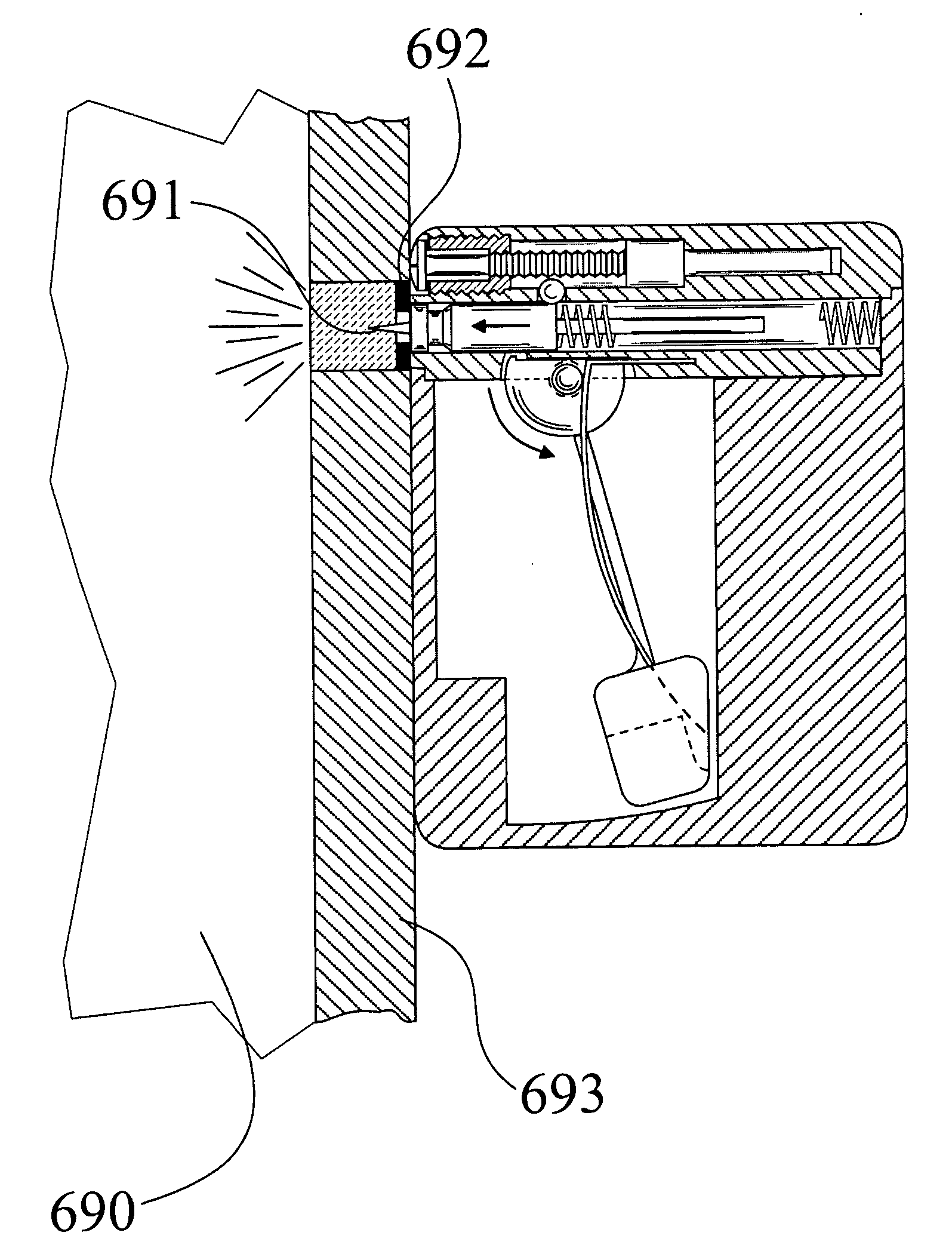
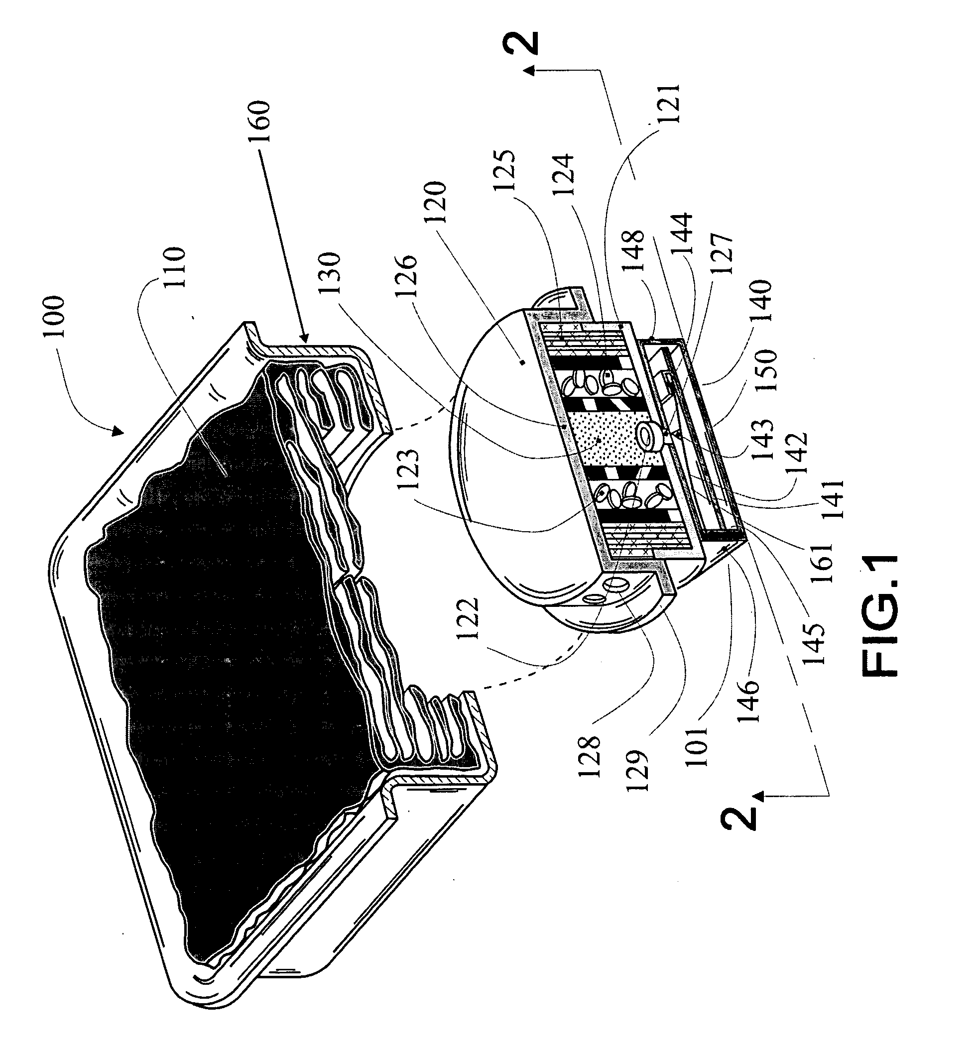
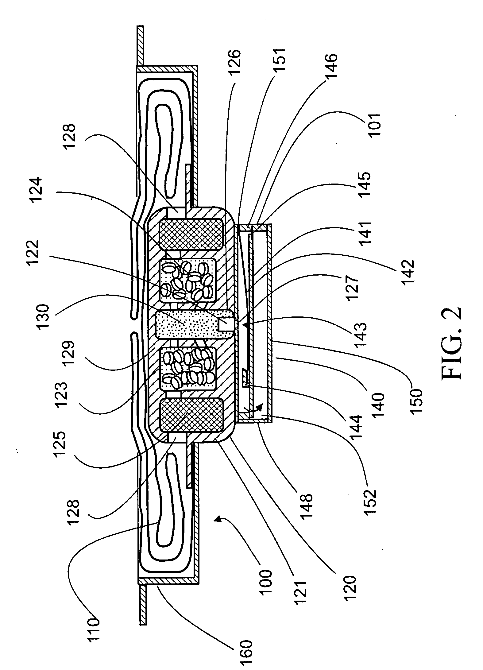
[0053]Referring to the accompanying drawings wherein like reference numerals refer to the same or similar elements, FIGS. 1 and 2 show an all-mechanical self-contained airbag system for mounting on the side of a vehicle to protect occupants in side impacts in accordance with the invention which is designated generally as 100. The airbag system 100 contains one or more inflatable airbags 110, an inflator assembly 120, a mounting plate 160 for mounting the airbag system 100 on the side of the vehicle and a sensor assembly 140 mounted to the inflator assembly 120. The sensor assembly 140 contains a rotatable, substantially planar sensing mass 141 and a cantilevered biasing spring 142 which performs the dual purposes of biasing the sensing mass 141 toward its at rest position shown in FIG. 2 and also providing the energy to the firing pin 143 required to initiate a stab primer 122 as further described below. The sensing mass 141 contains a firing pin spring-retaining portion 144 that re...


PUM


Abstract

Vehicle including an occupant protection apparatus for protecting an occupant in the event of an impact into a side of the vehicle and an electronic side impact crash sensor for detecting the side impact and which includes a sensor housing positioned to cause lateral movement of the sensor housing responsive to the side impact, a movable sensing mass within the sensor housing and move laterally relative to the sensor housing in response to the side impact, and a control unit connected to the crash sensor for activating the occupant protection apparatus. The crash sensor generates a signal representative of the movement of the sensing mass. The control unit includes a micro-processor and an algorithm processed by the micro-processor and configured to analyze the signal representative of the movement of the sensing mass and generate a deployment signal based thereon to initiate deployment of the occupant protection apparatus.

Description

CROSS REFERENCE TO RELATED APPLICATIONS[0001]This application is a divisional of U.S. patent application Ser. No. 10 / 331,060 filed Dec. 27, 2002 which is a continuation-in-part of U.S. patent application Ser. No. 09 / 435,045 filed Nov. 8, 1999, now U.S. Pat. No. 6,685,218, which is a continuation-in-part of U.S. patent application Ser. No. 09 / 114,962 filed Jul. 14, 1998, now U.S. Pat. No. 6,419,265 which is a continuation-in-part of U.S. patent application Ser. No. 08 / 101,017 filed Sep. 16, 1993, now U.S. Pat. No. 5,842,716.[0002]This application is related to U.S. patent application Ser. No. 10 / 768,791 filed Jan. 30, 2004, now U.S. Pat. No. 7,052,038, U.S. patent application Ser. No. 10 / 963,390 filed Oct. 12, 2004, now U.S. Pat. No. 7,025,379, U.S. patent application Ser. No. 11 / 058,337 filed Feb. 15, 2005, now U.S. Pat. No. 7,070,202, U.S. patent application Ser. No. 11 / 174,837 filed Jul. 5, 2005, now U.S. Pat. No. 7,097,201, and U.S. patent application Ser. No. 11 / 467,239 filed Au...

Claims


Application Information

Patent Timeline
IPC IPC(8): B60R21/0136B60J10/00B60N2/00B60N2/02B60N2/28B60R19/48B60R21/00B60R21/01B60R21/0132B60R21/015B60R21/16B60R21/20B60R21/21B60R21/33G01F23/00G01F23/20G01F23/296G07C5/00G07C5/08H01H35/14
CPCB60J10/00B60R21/0152B60N2/0232B60N2/0276B60N2/2863B60R19/483B60R21/0132B60R21/0136B60R21/20B60R21/21B60R21/33B60R2021/0011B60R2021/01325G07C5/008G07C5/0808H01H35/146B60R21/01558B60N2/002B60N2/02246
Inventor BREED, DAVID S.
Owner AMERICAN VEHICULAR SCI
Why Eureka
Try Eureka