Protective film forming method

a protective film and film thickness technology, applied in the direction of maintaining the head carrier alignment, recording information storage, instruments, etc., can solve the problems of difficult to achieve high recording density, difficult to pass the corrosion test mentioned above with a film thickness less than 2 nm, and deterioration of corrosion resistance, so as to improve corrosion resistance, reduce the distance between the magnetic head element and the magnetic disk, and improve the effect of corrosion resistan

Active Publication Date: 2009-05-28
SAE MAGNETICS (HK) LTD
View PDF9 Cites 4 Cited by
  • Summary
  • Abstract
  • Description
  • Claims
  • Application Information

AI Technical Summary

Benefits of technology

[0010]It is therefore an object of the present invention to improve the foregoing inconveniences and, in particular, to provide a high-quality protection target by forming a protective film that is thin and excellent in corrosion resistance.
[0016]It is possible for the insulating characteristic of the film itself to be deteriorated, since the film thickness is made thinner. However, the insulating characteristic can be secured by forming the insulating layer on the surface of the base film on which the diamond-like carbon film is to be formed. With this, the protective film with an excellent corrosion resistance can be formed. Therefore, it is possible to improve the quality of the protection target on which the protective film is formed. Furthermore, it is possible to secure the electric characteristic by suppressing the AC noise and the like of the protection target.
[0018]Further, the protective film forming method employs such a structure that elimination of the base film performed in the base film forming step is executed by an oblique incident ion beam etching method which irradiates an ion beam by tilting it with respect to a film-thickness direction of the base film. Furthermore, the protective film forming method comprises, before the base film forming step, a surface cleaning step for cleaning the surface of the protection target, and the surface cleaning step is executed by performing an oblique incident ion beam etching method which irradiates an ion beam by tilting it with respect to a film-thickness direction of the base film. With this, the energy applied by the ion beam to the surface form which the base film is eliminated or the surface to be cleaned, i.e., the protection target itself, can be suppressed. Thus, damages that may be imposed upon the protection target can be lightened. By cleaning the surface, a natural oxide film on the surface of the protection target can be eliminated, so that the adhesion property of the base film formed thereon can be improved.
[0023]By employing the present invention for the protective film of the magnetic head slider to be loaded on the hard disk drive, the film thickness of the protective film can be formed extremely thin so as to narrow the distance between the magnetic head element part and the magnetic disk. This makes it possible to improve the corrosion resistance. Therefore, it is possible to achieve high recording density of the hard disk drive and to improve the reliability at the same time.
[0024]The present invention is structured and functions in the manner described above. With this, the protective film that is extremely thin and has a suppressed film defect can be formed. Therefore, the present invention can provide such an excellent effect that it is possible to form the protective film with an excellent corrosion resistance and to improve the quality of the protection target on which the protection film is formed, which has not been achieved conventionally.

Problems solved by technology

However, when thickness of the protective film formed through the above-described steps, i.e., the protective film constituted with a double-layered film, is tried to be made thinner, it is difficult for such protective film to pass the corrosion tests mentioned above with the film thickness of less than 2 nm, for example.
Therefore, the protective film of the above-described structure cannot be made thinner because of its corrosion resistance, so that it is not possible to achieve high recording density.
Inversely, when the film of such protective film is thinned, the corrosion resistance is deteriorated.
This results in deteriorating the quality of the magnetic head slider.
However, the protective film disclosed in Patent Document 2 is the double-layered film as in the case of Patent Document 1, so that it is difficult for this protective film to pass the acid dipping test that has more strict conditions.
Therefore, it is still impossible with the protective film of Patent Document 2 to improve the corrosion resistance.

Method used


Image

  • Protective film forming method
  • Protective film forming method
  • Protective film forming method

Examples


first embodiment

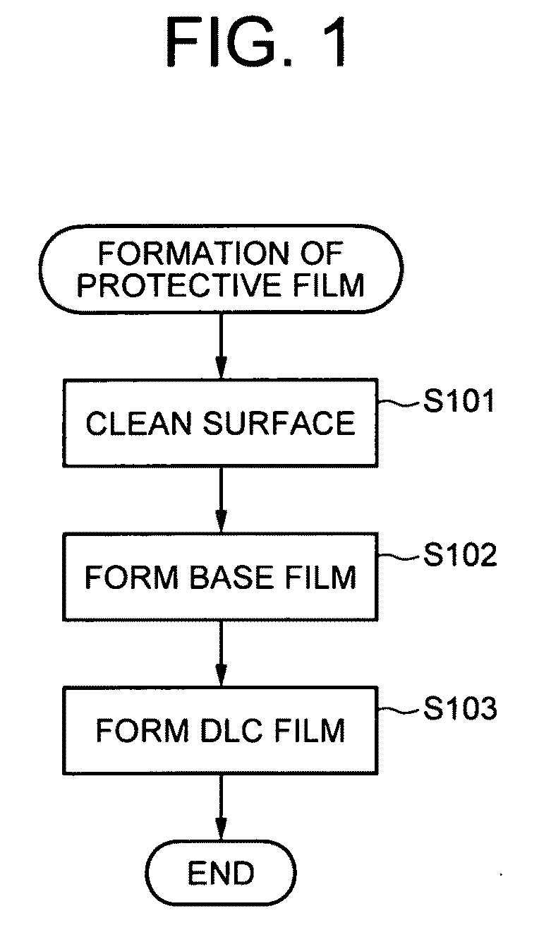
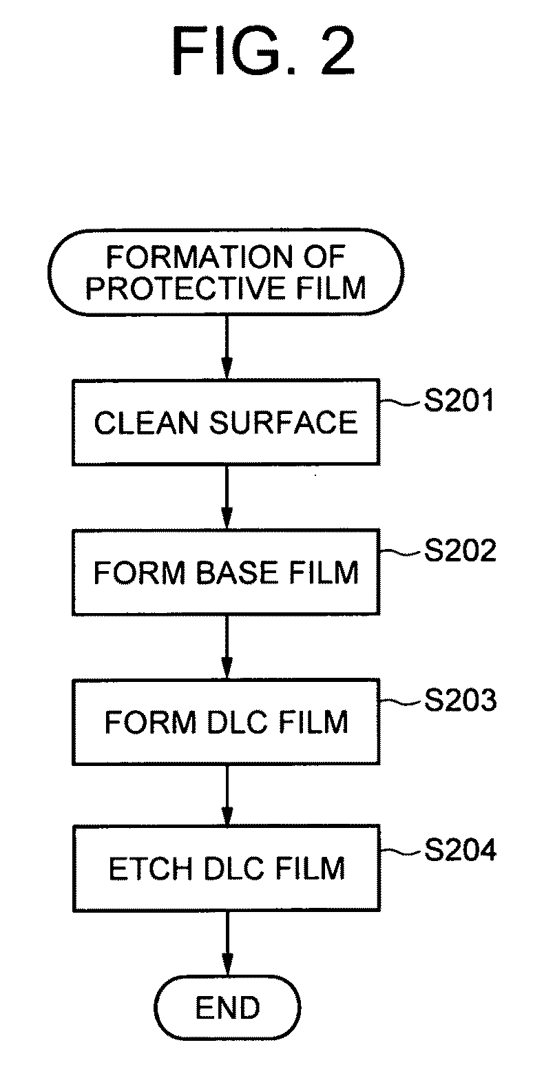
[0048]A first embodiment of the present invention will be described by referring to FIG. 3A-FIG. 11. FIG. 3A and FIG. 3B are illustrations showing a magnetic head slider as a protection target and a protective film formed thereon. FIG. 4 is a flowchart showing a procedure for manufacturing the magnetic head slider, and FIG. 5 is a flowchart showing a procedure for forming the protective film, which is a part of the procedure for forming the magnetic head slider. FIG. 6A-FIG. 6C are illustrations showing bar blocks having the connected magnetic head sliders as the targets for forming the protective films. FIG. 7A-FIG. 9B are illustrations showing each state when forming the protective film. FIG. 10 is a table showing forming conditions of the protective films, and FIG. 11 is an illustration showing results of experiments conducted on the magnetic head sliders that have the protective films formed thereon under each of the conditions.

[0049]The protection target in this embodiment is a...

second embodiment

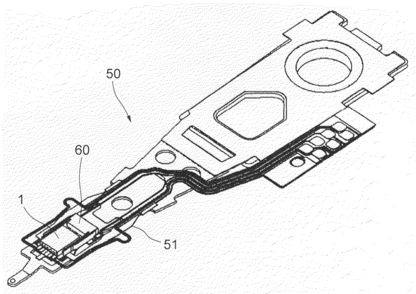
[0083]Next, a second embodiment of the present invention will be described by referring to FIG. 12-FIG. 13. FIG. 12 is an illustration showing a head gimbal assembly 50 on which the magnetic head slider 1 having the protective film 2 formed thereon by the protective film forming method described in the first embodiment is loaded. As shown in the illustration, the magnetic head slider 1 is loaded on the head gimbal assembly 50 by being mounted on a tongue face of a flexure 51, while being held to a micro actuator 60 that is loaded on the tongue face, for example. The head gimbal assembly 50 may be structured to have the magnetic head slider 1 loaded directly on the tongue face without having the micro actuator 60.

[0084]Further, FIG. 13 is an illustration showing a structure of a hard disk drive 100 on which the above-described head gimbal assembly 50 is loaded. The hard disk drive 100 comprises a plurality of disks, and comprises the head gimbal assemblies 50 by corresponding to each...


PUM

PropertyMeasurementUnit
thicknessaaaaaaaaaa
thicknessaaaaaaaaaa
thicknessaaaaaaaaaa

Abstract

To provide a high-quality protection target by forming a protective film that is thin and excellent in corrosion resistance. Provided is a protective film forming method for forming a protective film at least on a surface of a protection target. The method comprises: a base film forming step for forming a base film on the surface of the protection target; and a DLC film forming step for forming a diamond-like carbon film on the base film. The base film forming step forms the base film on the surface of the protection target for a plurality of times by repeating a process of depositing the base film in a prescribed thickness and eliminating a part of or a whole part of the base film. Further, the method comprises, before the DLC film forming step, an insulating layer forming step for forming an insulating layer on the surface of the base film on which the diamond-like carbon film is to be formed.

Description

BACKGROUND OF THE INVENTION[0001]1. Field of the Invention[0002]The present invention relates to a protective film forming method and, more specifically, to a method for forming a thin protective film on a surface of a protection target.[0003]2. Description of the Related Art[0004]Recently, in order to implement size-reduction and large capacity, there has been a rapid advancement in increasing the recording density of magnetic disk devices. Accordingly, it is required to decrease distance between a magnetic head slider and a magnetic disk, i.e., to decrease floating amount of the magnetic head slider further with respect to the magnetic disk.[0005]In the meantime, a decrease in the floating amount of the magnetic head slider with respect to the magnetic disk may increase a chance for the magnetic head slider to be in contact or to be collided with a magnetic head face that is being rotated at a high speed. Thus, it is necessary to form a protective film on a floating face of the ma...

Claims


Application Information

Patent Timeline
Patent Type & Authority Applications(United States)
IPC IPC(8): G11B5/127G11B5/60B05D5/00C23F1/02B05D3/06C23C14/34
CPCC23C16/0272C23C16/26G11B5/6005G11B5/3173G11B5/40G11B5/3106G11B5/6082
Inventor UEDA, KUNIHIROFANG, HONG XINWANG, DONGKONISHI, YOSHIYUKIUENO, SATOKOOKADA, SHIGENOBU
Owner SAE MAGNETICS (HK) LTD
Why Eureka
Try Eureka