Method and device for three dimensional microdissection

Active Publication Date: 2009-06-04
MMI MOLECULAR MACHINES & INDS
View PDF6 Cites 13 Cited by
  • Summary
  • Abstract
  • Description
  • Claims
  • Application Information

AI Technical Summary

Benefits of technology

[0045]Preferably, the optical axis of the laser stands perpendicular on rotary axis R, whereby rotary axis R and V coincide and stand perpendicular on axis H. The perpendicular or parallel arrangement of the axes can be executed with a high level of accuracy. In addition, such an a

Problems solved by technology

Larger volumes with correspondingly greater layer thicknesses are not separable using known laser microdissection methods.
Even preparation of the sample typically leads to changes and degeneration in the material to be examined in the last step of the process.
In addition, it is not possible in the known laser-based microdissection methods to deep-freeze the sample during the entire treatment process.
Nevertheless, it is difficult to cut deep-frozen materials mechanically.
Furt

Method used


Image

  • Method and device for three dimensional microdissection
  • Method and device for three dimensional microdissection

Examples


Embodiment Construction

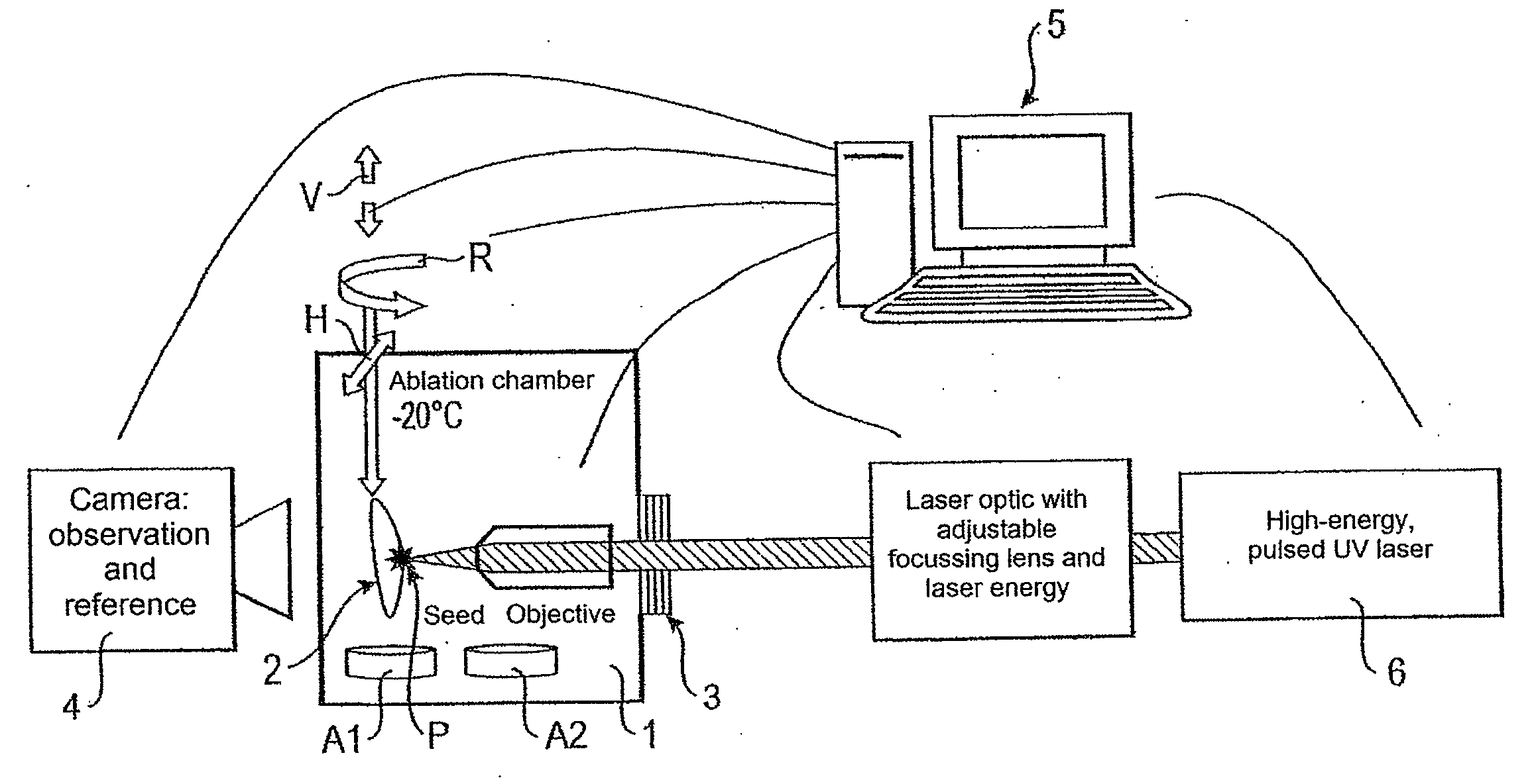
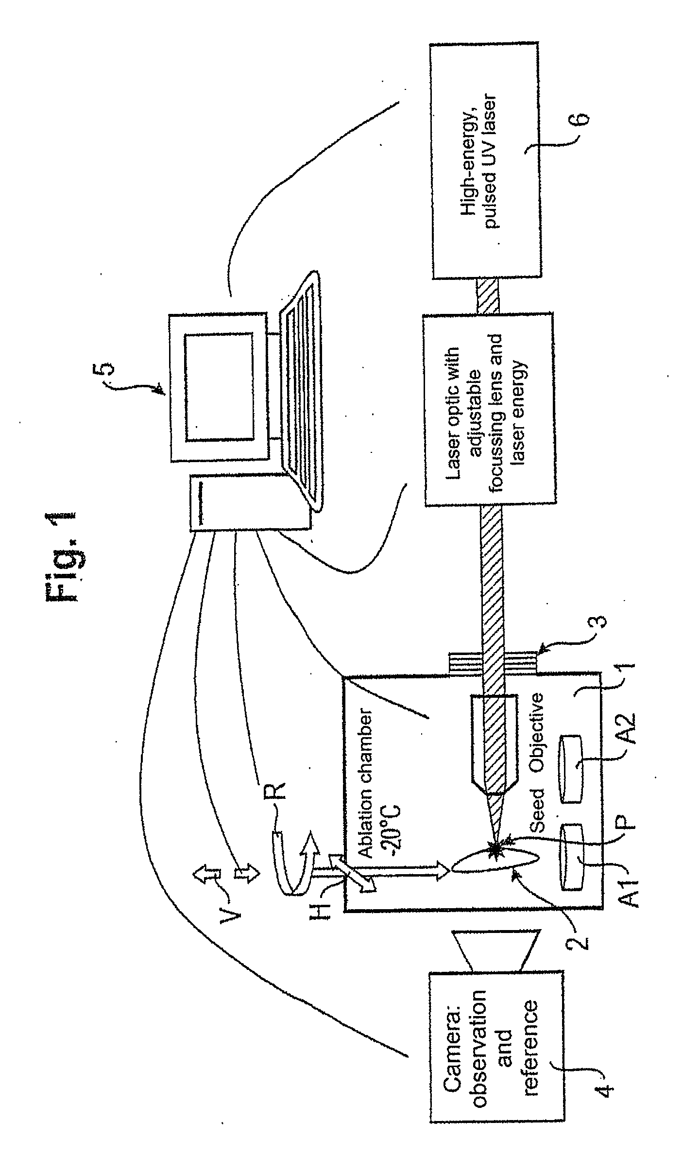
[0053]FIG. 1 shows schematically a device for the separation of defined, three-dimensional structures from a sample according to an embodiment of the invention. The volume to be enucleated is also termed in the following as VOI (volume of interest).

[0054]In the present embodiment, a sample head with a sample 2 is located in an ablation chamber 1. Ablation chamber 1 comprises a housing in which the enucleation of defined, three-dimensional structures from the sample is performed. The sample head is disposed movably along a vertical axis V and a horizontal axis H and rotatably about a rotary axis R. Axes V and R may, as in the present embodiment, be identical. The movements of the sample head along axis V and H and about axis R are motorised by means of appropriate positioning devices which are not illustrated in FIG. 1. According to this embodiment, the sample head and the sample are movable by three degrees of freedom. The sample holder, for example, may be a mechanical holder or ma...


PUM


Abstract

A method for three-dimensional microdissection for the separation of defined structures in the sub-millimeter range by means of cold laser ablation or by means of multi-photon absorption, whereby exposure of the structures to be separated is performed using directional information in all spatial directions. In addition, a 3D microdissection system for the separation of defined, three-dimensional structures from a sample, having: a control unit (5); an ablation chamber (1) with a sample holder provided therein, on which the sample to be processed is to be mounted and which is movable along a linear axis V and rotatable about a rotary axis R, whereby the sample holder is provided with positioning devices that are connected to the control unit which can cause the positioning devices to move the sample holder along another linear axis H and to rotate it about rotary axis R, and a laser device (6), which is introduced into the ablation chamber at least partially through a laser window (3) that is provided in the ablation chamber. The ablation chamber is connected to the control unit and has an adjustable optic, which can be adjusted by means of the control unit such that the laser beam is focussed in the region of the sample.

Description

[0001]The following disclosure is based on European Patent Application No. 07 020 582.8, filed on Oct. 22, 2007, which is incorporated into this application by reference.FIELD OF AND BACKGROUND[0002]The present invention relates to a method for the separation of defined, three-dimensional structures especially from biological objects and a device for performing this method.[0003]Microdissection permits the targeted isolation of mainly biological material from a sample. Typically in the prior art, mechanical or two-dimensional laser-based microdissection methods and devices are employed, using which it is possible to cut out and capture defined structures from the mainly biological samples.[0004]A two-dimensional, laser-based microdissection method is described, for example, in DE 10 2006 000 934 A1. A biological preparation, a histological tissue section for example, is mounted therein on a carrier. Subsequently, selection of the preparation takes place by means of laser irradiation...

Claims


Application Information

Patent Timeline
IPC IPC(8): G01J1/58G01B11/14
CPCG01N1/06G01N2001/2886G01N1/42G01N1/2813
Inventor NIEHREN, STEFAN
Owner MMI MOLECULAR MACHINES & INDS
Why Eureka
Try Eureka