Process for producing mold
a mold and mold technology, applied in the field of mold production, can solve the problems of reducing the efficiency of forming a fine pattern and forming a seam between
- Summary
- Abstract
- Description
- Claims
- Application Information
AI Technical Summary
Benefits of technology
Problems solved by technology
Method used
Image

Examples
synthesis example 1
[0249]Into a glass autoclave, 100 g of CF2═CFOCF2CF2CF═CF2 as a diene monomer, 0.5 of methanol as a chain transfer agent and 0.7 g of ((CH3)2CHOCOO)2 as a polymerization initiator, were introduced and cyclopolymerized by a suspension polymerization method to obtain a polymer A which is a fluorocyclopolymer and also a perfluoropolymer (F). The intrinsic viscosity [η] of the polymer A was 0.34 dL / g in perfluoro(2-butyltetrahydrofuran) at 30° C.
[0250]The polymer A was heat-treated in a circulating hot air oven at 300° C. for 1 hour in the air, and then, the functional groups of molecular terminals were treated by impregnation in ultrapure water at 110° C. for 1 week, followed by drying in a vacuum dryer at 100° C. for 24 hours to obtain a polymer A1 as a perfluoropolymer (F1). In the IR spectrum of the polymer A1, there was a peak belonged to a carboxy group. Further, the light transmittance at a wavelength of from 400 to 2,000 nm was at least 95% with the thickness of 100 μm. The fluo...
synthesis example 2
[0251]Into a 1L stainless steel autoclave, 5 g of the polymer A1 was introduced, and after the inside of the autoclave was flushed for 3 times with nitrogen, the pressure was reduced to 4 KPa. Then, a fluorine gas diluted to 14 vol % with nitrogen was introduced in the autoclave until 101 KPa, and fluorination treatment was carried out at 230° C. for 6 hours to obtain 5 g of a polymer A2 as a perfluoropolymer (F2). In the IR spectrum of the polymer A2, there was no peak showing e.g. a hydrocarbon group or a carboxy group of a molecular terminal derived from a polymerization initiator. The fluorine content of the polymer A2 was 68 mass % in the polymer A2 (100 mass %). The contact angle of water with a film made of the polymer A2 was 1160.
example 1
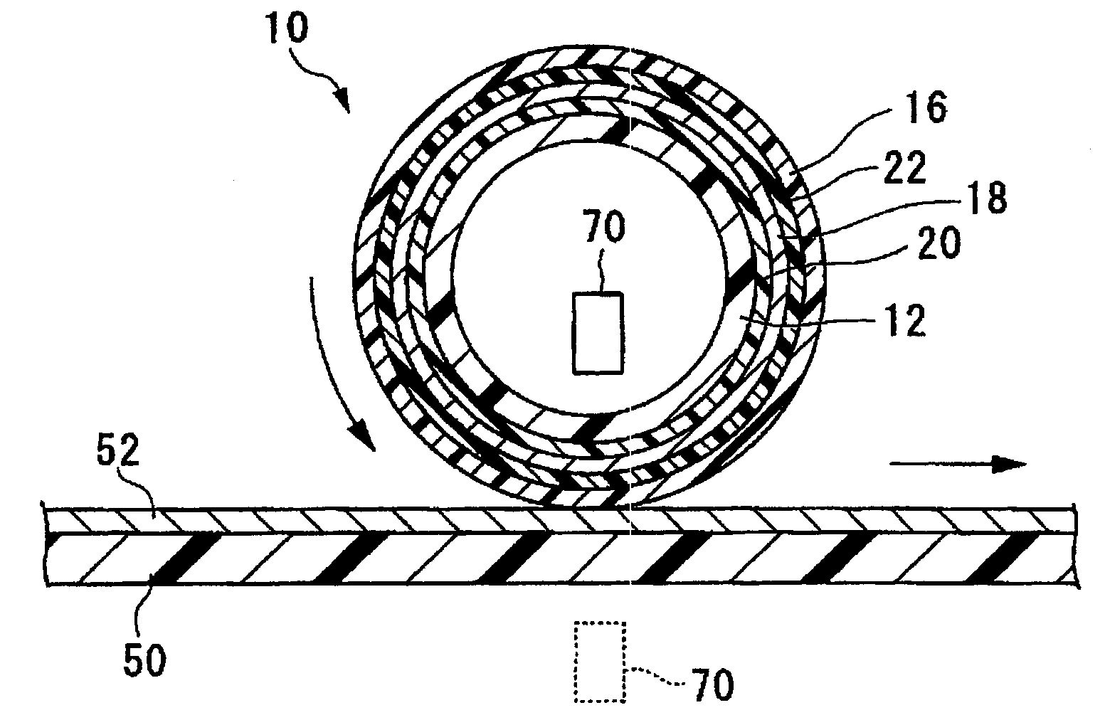
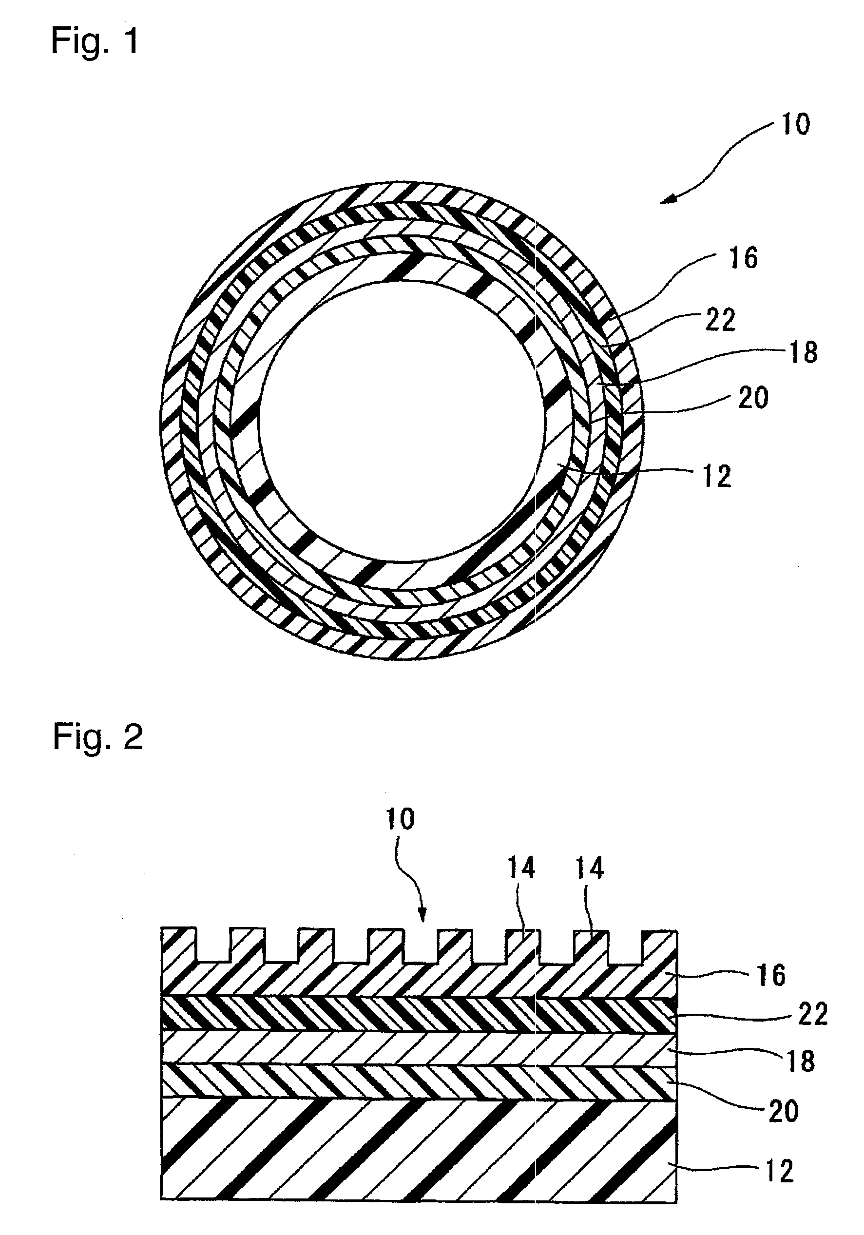
[0252]An antistatic agent (CONISOL F205 manufactured by TA Chemical Co., Ltd.) is diluted by 5 times in a solvent mixture of water / isopropanol ( 1 / 7 mass ratio) to prepare an antistatic agent for coating. The antistatic agent is applied on the circumferential surface of an acrylic resin pipe (1.8 mm in thickness, 30 mm in diameter and 150 mm in length) by rotating the pipe at a rate of 120 rpm by a spray coating method, followed by drying with a dryer to form an antistatic layer. The surface resistance of the antistatic layer is 109Ω / □.
[0253]The polymer A1 is dissolved in perfluorotributylamine to prepare a 1 mass % solution of the polymer A1, and the solution is filtrated by a polytetrafluoroethylene (PEFE) membrane filter having a pore diameter of 0.2 μm. The solution is applied on a surface of the antistatic layer by rotating the pipe at a rate of 120 rpm by a spray coating method for 1 minute, followed by drying with a dryer to form a second primer layer.
[0254]The polymer A2 is ...
PUM
| Property | Measurement | Unit |
|---|---|---|
| thickness | aaaaa | aaaaa |
| transmittance | aaaaa | aaaaa |
| thickness | aaaaa | aaaaa |
Abstract
Description
Claims
Application Information
 - R&D
- Intellectual Property
- Life Sciences
- Materials
- Tech Scout
- Unparalleled Data Quality
- Higher Quality Content
- 60% Fewer Hallucinations
Browse by: Latest US Patents, China's latest patents, Technical Efficacy Thesaurus, Application Domain, Technology Topic, Popular Technical Reports.
© 2025 PatSnap. All rights reserved.Legal|Privacy policy|Modern Slavery Act Transparency Statement|Sitemap|About US| Contact US: help@patsnap.com