
Method for manufacturing soi substrate

a technology of soi and substrate, which is applied in the direction of basic electric elements, electrical apparatus, semiconductor devices, etc., can solve the problems of reduced separation substrate quality, easy to cause defective bonding, and defective bonding, so as to reduce defective bonding, reduce quality differences between a plurality of soi substrates, and suppress damage to separation substrates

Inactive Publication Date: 2009-06-04
SEMICON ENERGY LAB CO LTD
View PDF7 Cites 11 Cited by
  • Summary
  • Abstract
  • Description
  • Claims
  • Application Information

AI Technical Summary

Benefits of technology

[0009]However, when the characteristics (such as thermal expansion coefficient and the amount of bent) of the separation substrate and the substrate to be separated are different, defective bonding might be caused due to heat treatment or the like which is performed after bonding. In particular, when a substrate other than a semiconductor substrate (e.g., a glass substrate) is used as a substrate to be separated, materials of the substrates are different, and thus defective bonding is easily caused.
[0010]Moreover, when the same separation substrate is used repeatedly (reused), the quality of the separation substrate is reduced due to repeated heat treatment or the like, and thus the quality of an SOI substrate manufactured using the separation substrate might be reduced. Therefore, a significant difference might be caused between a first-manufactured SOI substrate and a last-manufactured SOI substrate, which are manufactured using one silicon wafer. Furthermore, when as many SOI substrates as possible are intended to be manufactured using one silicon wafer, the thickness of the substrate is reduced as the number of reuse is increased, and thus the separation substrate might be broken in a manufacturing process or the incidence rate of defective bonding might be increased.
[0011]In view of the above-described problems, it is an object of the present invention to reduce defective bonding when manufacturing an SOI substrate including a substrate formed of an insulator. It is another object of the present invention to suppress damage of a separation substrate and reduce quality differences between a plurality of SOI substrates when manufacturing the plurality of SOI substrates.
[0018]The present invention makes it possible to reduce defective bonding even when manufacturing an SOI substrate including a substrate formed of an insulator. Moreover, the present invention makes it possible to suppress damage of a separation substrate and reduce quality differences between a plurality of SOI substrates even when manufacturing the plurality of SOI substrates.

Problems solved by technology

However, when the characteristics (such as thermal expansion coefficient and the amount of bent) of the separation substrate and the substrate to be separated are different, defective bonding might be caused due to heat treatment or the like which is performed after bonding.
In particular, when a substrate other than a semiconductor substrate (e.g., a glass substrate) is used as a substrate to be separated, materials of the substrates are different, and thus defective bonding is easily caused.
Moreover, when the same separation substrate is used repeatedly (reused), the quality of the separation substrate is reduced due to repeated heat treatment or the like, and thus the quality of an SOI substrate manufactured using the separation substrate might be reduced.
Therefore, a significant difference might be caused between a first-manufactured SOI substrate and a last-manufactured SOI substrate, which are manufactured using one silicon wafer.
Furthermore, when as many SOI substrates as possible are intended to be manufactured using one silicon wafer, the thickness of the substrate is reduced as the number of reuse is increased, and thus the separation substrate might be broken in a manufacturing process or the incidence rate of defective bonding might be increased.

Method used


Image

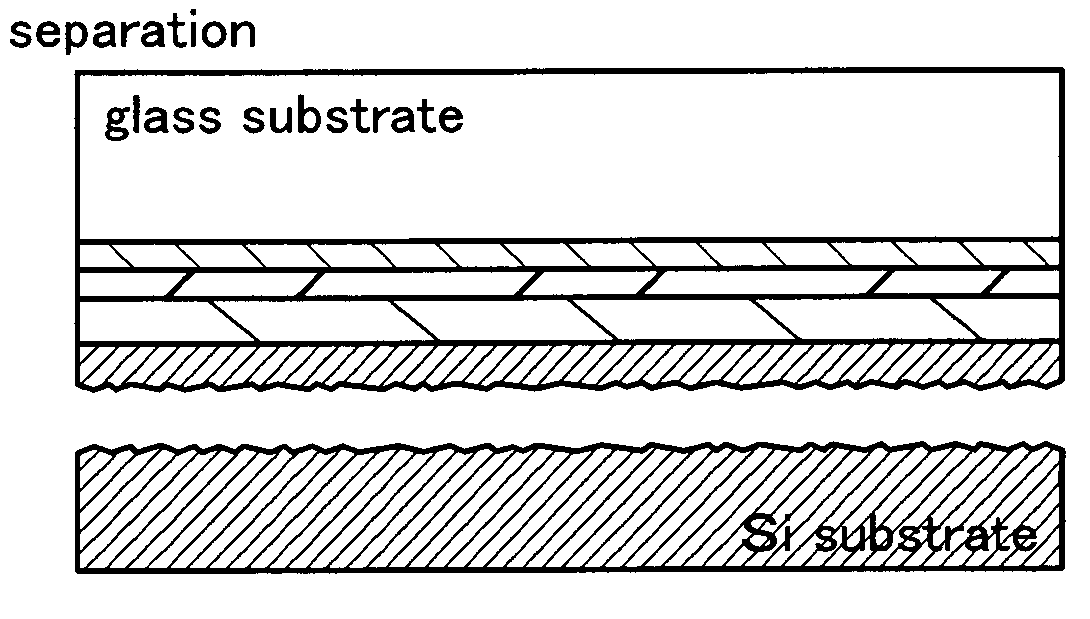
  • Method for manufacturing soi substrate
  • Method for manufacturing soi substrate
  • Method for manufacturing soi substrate

Examples


embodiment mode 1

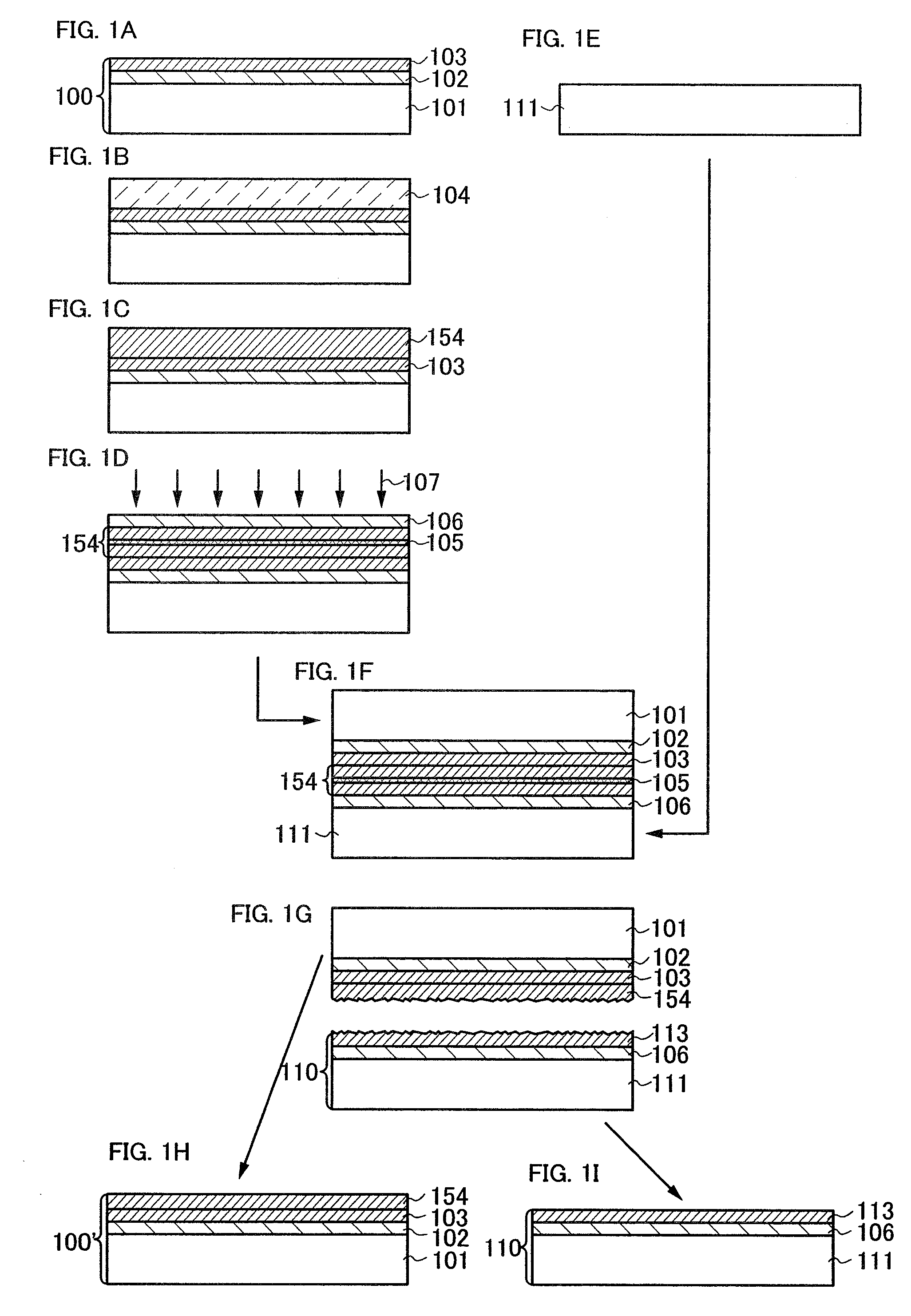
[0037]In this embodiment mode, an example of a method for manufatcuring an SOI substrate of the present invention will be described with reference to drawings.

[0038]First, a first SOI substrate 100 is prepared (see FIG. 1A).

[0039]In the first SOI substrate 100, a first single crystal semiconductor film 103 is provided over a first substrate 101 with an insulating film 102 interposed therebetween. Here, the first SOI substrate 100 serves as a separation substrate.

[0040]As the first substrate 101, a substrate formed of an insulator is used. Specifically, as the first substrate 101, a glass substrate used in the electronics industry, such as an aluminosilicate glass substrate, an aluminoborosilicate glass substrate, or a barium borosilicate glass substrate is used. Alternatively, a plastic substrate which has heat resistance against a processing temperature of this process and has an insulating film (e.g., a silicon oxide film or a silicon oxynitride film) on its surface can be used. W...

embodiment mode 2

[0070]In this embodiment mode, a method for manufacturing a plurality of SOI substrates and usage of the substrate will be described with reference to drawings.

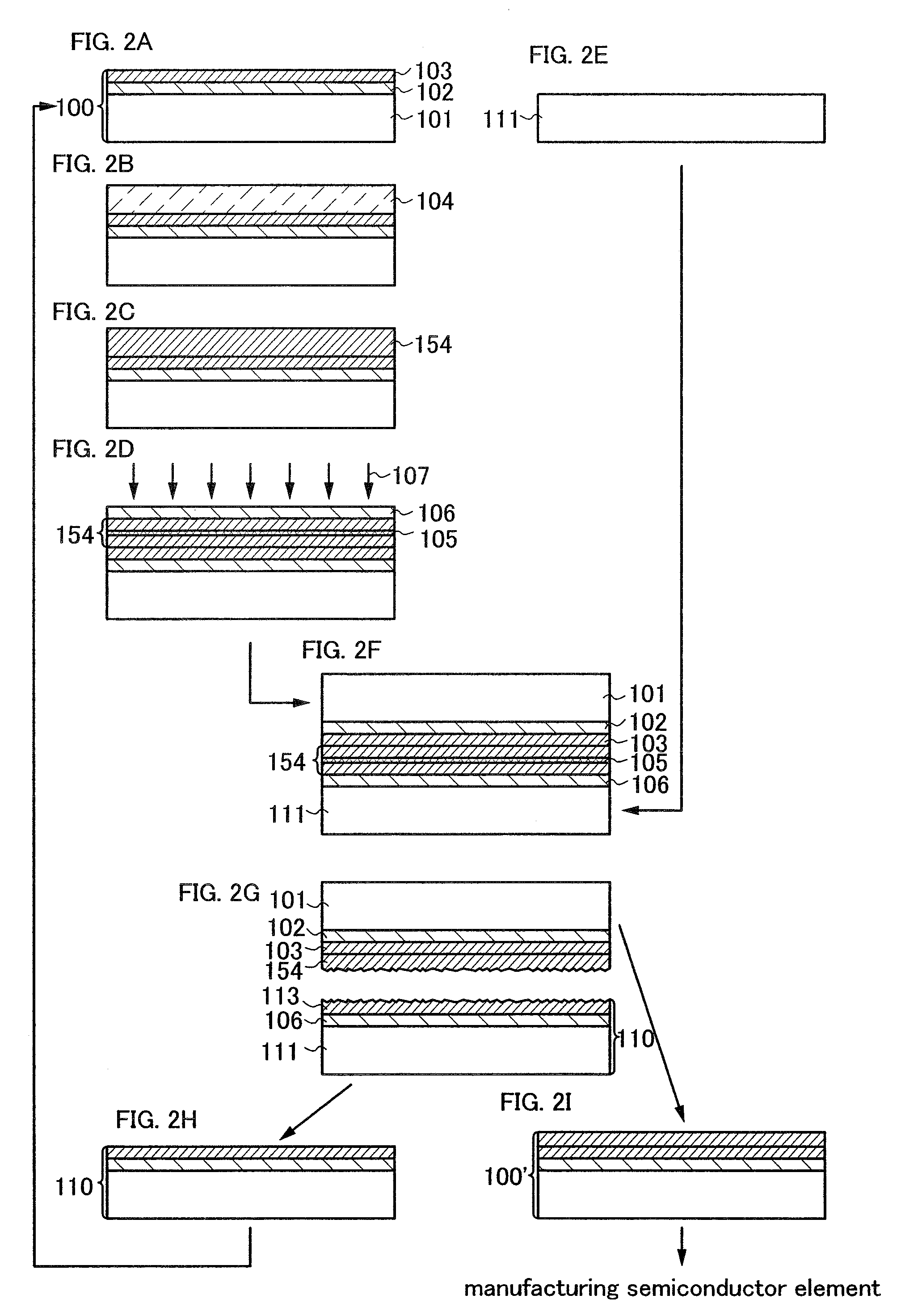
[0071]First, the first SOI substrate 100 which serves as a separation substrate and the second substrate 111 are prepared, and after the second single crystal semiconductor film 154 is formed over the first SOI substrate 100, the separation layer 105 is formed in the second single crystal semiconductor film 154, and the insulating film 106 is formed over the second single crystal semiconductor film 154 (see FIGS. 2A to 2E, hereinafter denoted by “Process A”). Note that the steps of FIGS. 2A to 2E may be performed similarly to the above-described steps of FIGS. 1A to 1E.

[0072]Next, after a surface of the insulating film 106 which serves as a bonding layer and a surface of the second substrate 111 are bonded to each other, heat treatment is performed, and thus cleavage occurs at the separation layer 105, so that the third singl...

embodiment mode 3

[0082]In this embodiment mode, a method for manufacturing an SOI substrate which is different from that described in the above emodiment modes will be described with reference to drawings. Specifically, a method which is different from that in the above embodiment modes will be described as for a method in which a semiconductor film is formed over a first single crystal semiconductor film and the semiconductor film is epitaxially grown (gas phase grown) at the same time as its deposition to form a second single crystal semiconductor film.

[0083]By formation of a semiconductor film (e.g., a silicon film) over a single crystal semiconductor film (e.g., a single crystal silicon film) by a CVD method under predetermined conditions, the semiconductor film to be formed can be epitaxially grown (gas phase grown) using the single crystal silicon film as a seed layer at the same time as its deposition.

[0084]For example, after the above-described steps of FIGS. 2A to 2G are performed, a semico...


PUM


Abstract

A second single crystal semiconductor film is formed over a first single crystal semiconductor film; a separation layer is formed by addition of ions into the second single crystal semiconductor film; a second insulating film functioning as a bonding layer is formed over the second single crystal semiconductor film; a surface of a first SOI substrate and a surface of a second substrate are made to face each other, so that a surface of the second insulating film and the surface of the second substrate are bonded to each other; and then heat treatment is performed to cause cleavage at the separation layer, so that a second SOI substrate in which a part of the second single crystal semiconductor film is provided over the second substrate with the second insulating film interposed therebetween is formed.

Description

BACKGROUND OF THE INVENTION[0001]1. Field of the Invention[0002]The present invention relates to a method for manufacturing an SOI (silicon on insulator) substrate and a method for manufacturing a semiconductor device.[0003]2. Description of the Related Art[0004]In recent years, integrated circuits using an SOI (silicon on insulator) substrate in which a thin single crystal semiconductor film is formed on its insulating surface, instead of a bulk silicon wafer, have been developed. Since parasitic capacitance between a drain of a transistor and a substrate is reduced with use of the SOI substrate, the SOI substrate has been attracted attention as a substrate which improves performance of semiconductor integrated circuits.[0005]Smart Cut (registered trademark) method is known as one of methods for manufacturing an SOI substrate (for example, see Patent Document 1: Japanese Published Patent Application No. 2000-124092). An outline of a method for manufacturing an SOI substrate by Smar...

Claims


Application Information

Patent Timeline
Patent Type & Authority Applications(United States)
IPC IPC(8): H01L21/762
CPCH01L21/2007H01L21/32115H01L29/66772H01L27/1214H01L27/1266H01L21/76254H01L27/12H01L21/20
Inventor ISAKA, FUMITOKATO, SHOKOMATSU, RYUNEI, KOSEISHIMOMURA, AKIHISA
Owner SEMICON ENERGY LAB CO LTD
Learn More