

Liquid crystal optical device and process for its production
a technology of optical devices and liquid crystals, applied in liquid crystal compositions, chemistry apparatuses and processes, instruments, etc., can solve the problems of insufficient transparency of the panel, high haze value of the device in a transparent state, etc., and achieve excellent stability in transparent scattering characteristics and productivity, and low haze value
- Summary
- Abstract
- Description
- Claims
- Application Information
AI Technical Summary
Benefits of technology
Problems solved by technology
Method used
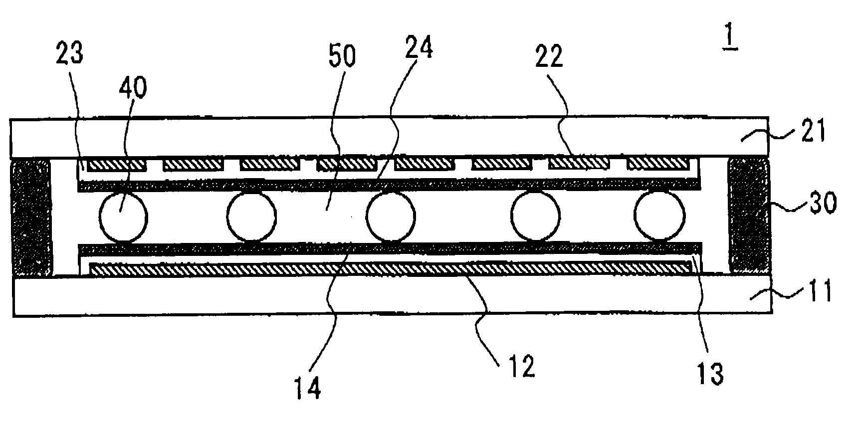
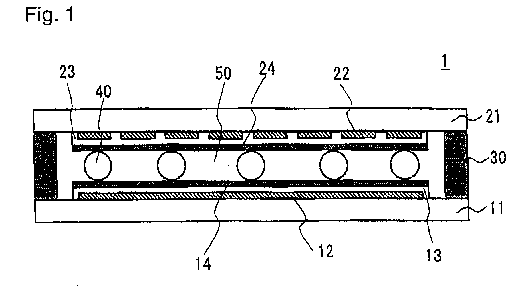
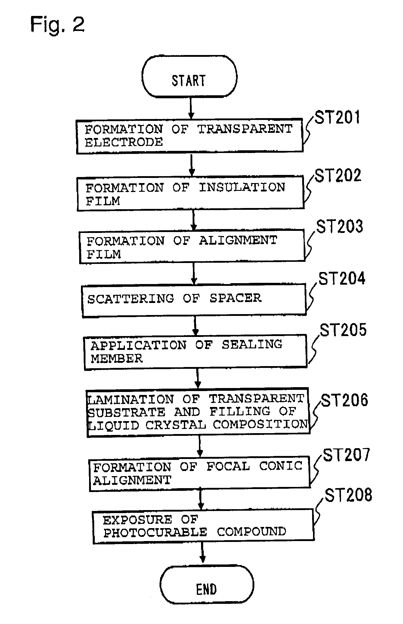
Image

Examples
example 1
[0084]To nematic liquid crystal (product name BL-002 manufactured by Merck Co., Inc., Tc=72° C., Δn=0.246, Δ∈=16) showing positive dielectric anisotropy, a dextro-rotatory optically active material (Paliocolor LC756 manufactured by BASF Corporation, HTP in the nematic liquid crystal is 56) was added to form chiral nematic liquid crystal having the helical pitch of 2 μm. The above dextro-rotatory optical active material is a photo-curable compound, and its content in the above liquid crystal composition is 1.0 mass %. Further, a photo-polymerization initiator (benzoin isopropyl ether) is added in an amount of about 1.0 mass % to the photocurable compound contained in the above liquid crystal composition, to obtain the liquid crystal composition (liquid crystal composition A) according to the present invention. The N-I phase transition temperature of the liquid crystal composition A was 68° C.
[0085]Then, on ITO electrodes respectively provided on a pair of glass substrates each having...
example 2
[0088]The liquid crystal composition A prepared in Example 1 was injected into a cell in the same manner as in Example 1 by a vacuum injection method, and the injection hole was sealed. Then, to the electrode terminal portions of the cell, a bipolar pulse in rectangular waveform having an effective value of 8 V and a pulse width of 500 ms was applied, and the cell became an opaque state in white and showed a uniform light scattering state. In a state of no voltage application, cell showing a light scattering state was exposed to UV light to cure a curable compound thereby to obtain a liquid crystal optical device.
[0089]After the exposure of UV light, the liquid crystal optical device showed an opaque state in white in the same manner, and the light scattering performance was somewhat improved. Then, between the above pair of ITO electrodes, voltage of 60 V at 200 Hz in rectangular waveform was applied, and as a result, the liquid crystal optical device became transparent, and when t...
example 3
[0090]To the same nematic liquid crystal showing positive electric anisotropy as in Example 1, the same dextro-rotatory optical active material as in Example 1 was added to obtain chiral nematic liquid crystal having a helical pitch of 1 μm. The above dextro-rotatory optically active material is a photo-curable compound, and the content in the above liquid crystal composition is 1.8 mass %. Further, in the same manner as in Example 1, about 1 mass % of a photo-polymerization initiator was added to a photo-curable compound contained in the above liquid crystal composition, whereby the liquid crystal composition (liquid crystal composition B) in the present invention was obtained.
[0091]Then, the liquid crystal composition B was injected into the same cell as in Example 1 by a vacuum injection method to seal the injection hole. Then, a bipolar pulse in rectangular waveform having an effective value of 12 V and a pulse width of 500 ms was applied to the electrode terminal portions of th...
PUM
| Property | Measurement | Unit |
|---|---|---|
| thickness | aaaaa | aaaaa |
| diameter | aaaaa | aaaaa |
| diameter | aaaaa | aaaaa |
Abstract
Description
Claims
Application Information