Multi-energy imaging system and method using optic devices

a multi-energy imaging and optic device technology, applied in the field of optics, can solve the problems of low detection accuracy, low detection accuracy, and low detection accuracy of edxrd systems

Inactive Publication Date: 2009-06-11
GENERAL ELECTRIC CO
View PDF25 Cites 40 Cited by
  • Summary
  • Abstract
  • Description
  • Claims
  • Application Information

AI Technical Summary

Problems solved by technology

Such EDXRD systems may suffer from high false positives due to weak diffracted X-ray signals.
Third, some of the materials being searched for, e.g., explosives, may not diffract strongly as they are amorphous.
Fourth, the diffracting volume may be small.
The last two limitations arise from the type of threat materials being searched for in baggage, making all but the second limitation unavoidable.
These types of optics typically do not provide much gain at energy levels above 80 keV, since the difference in the indices of refraction between air and glass becomes increasingly small as energy levels approach and surpass 80 keV.
Thus, known optics are limited in their potential uses.
This biasing manifests as artifacts in any images reconstructed from the attenuation data, such as those attributed to beam hardening in computed tomography.
A challenge lies in the sequential nature of such an examination, where image data are generated, for example, first with one spectrum and then with another spectrum.
For many applications where high throughput is critical, sample composition is dynamic, and / or sample positioning may preclude repetitive scanning, the logistics of physically scanning an object twice may be unacceptable.
Such methodologies are limited in the degree to which attenuation can produce cleanly separated energy intervals, severely restricting the sensitivity of this approach for analyzing different materials.
High voltage modulation to produce different spectral characteristics also has been implemented in some cases with limited success.
There is a challenge in both approaches to mitigate registration differences in the image reconstruction projections that result from sample movement between data sets acquired at different energies, as well as a slight misalignment of the X-ray paths that traverse the object, as is incurred with modulating the X-ray beam on a sub-view basis.

Method used


Image

  • Multi-energy imaging system and method using optic devices
  • Multi-energy imaging system and method using optic devices
  • Multi-energy imaging system and method using optic devices

Examples


Embodiment Construction

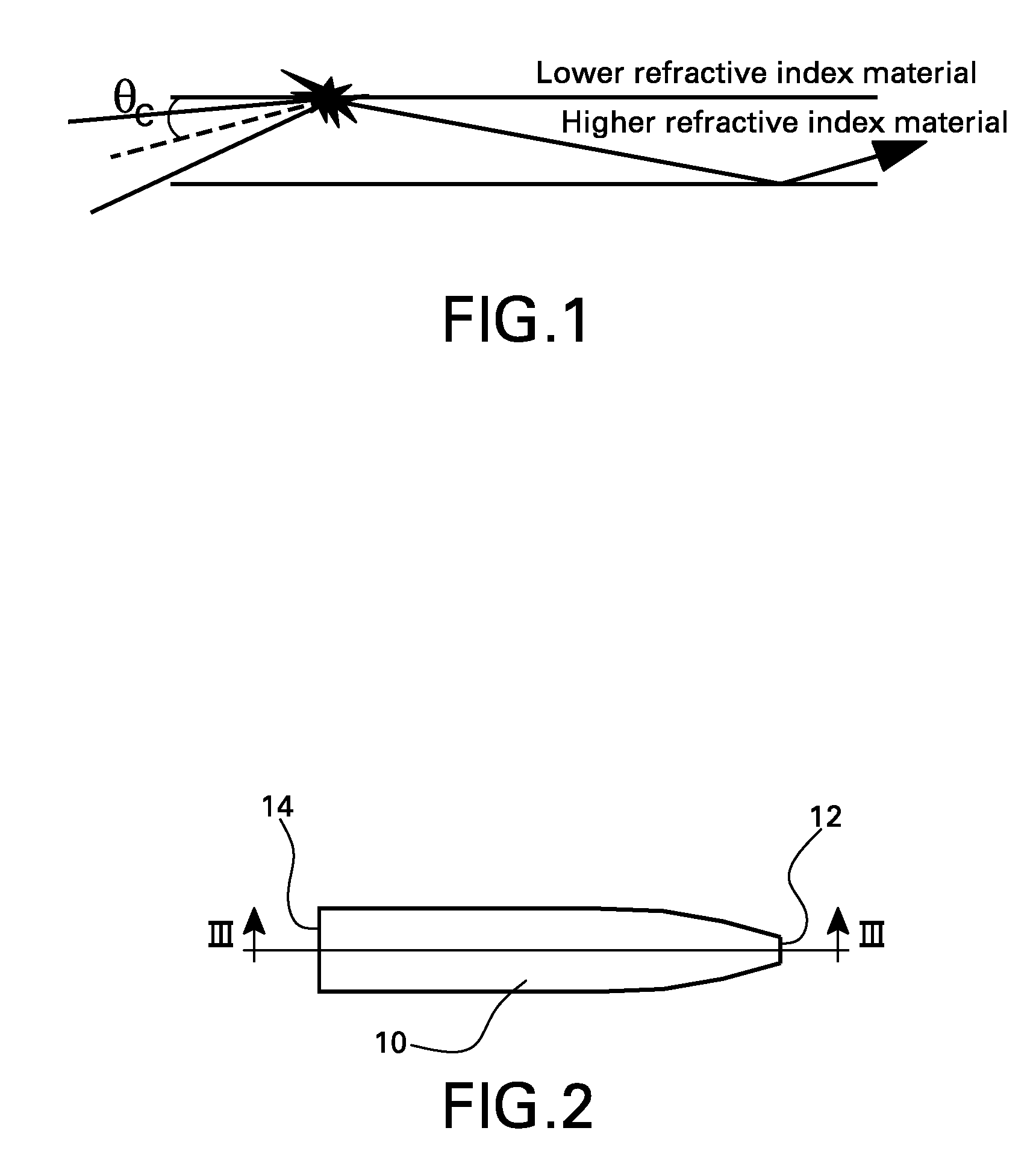
[0035]Embodiments of the invention described herein primarily utilize the phenomenon of total internal reflection. Referring to FIG. 1, when an angle of incidence is less than a critical angle θc, total internal reflection occurs. The critical angle θc for total internal reflection depends on, among other factors, the selection of materials, the difference in the relative indices of refraction between the materials, the material photon absorption properties, and the energy of the incident photons. By appropriate material selection in the multilayer optic described herein, the critical angle θc can be increased several times over an air-glass critical angle, allowing many more photons to satisfy the condition for total internal reflection. This will allow a greater photon transmission through a multilayer optic than is possible with, for example, polycapillary optics.

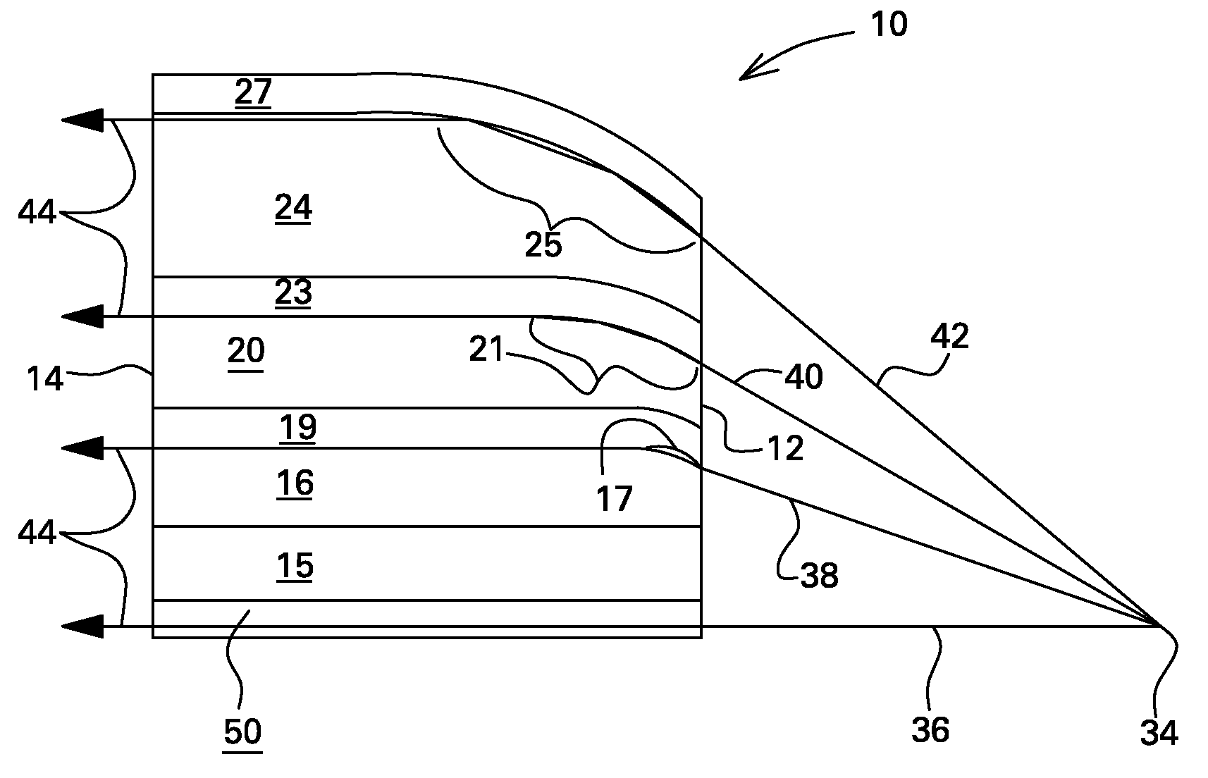
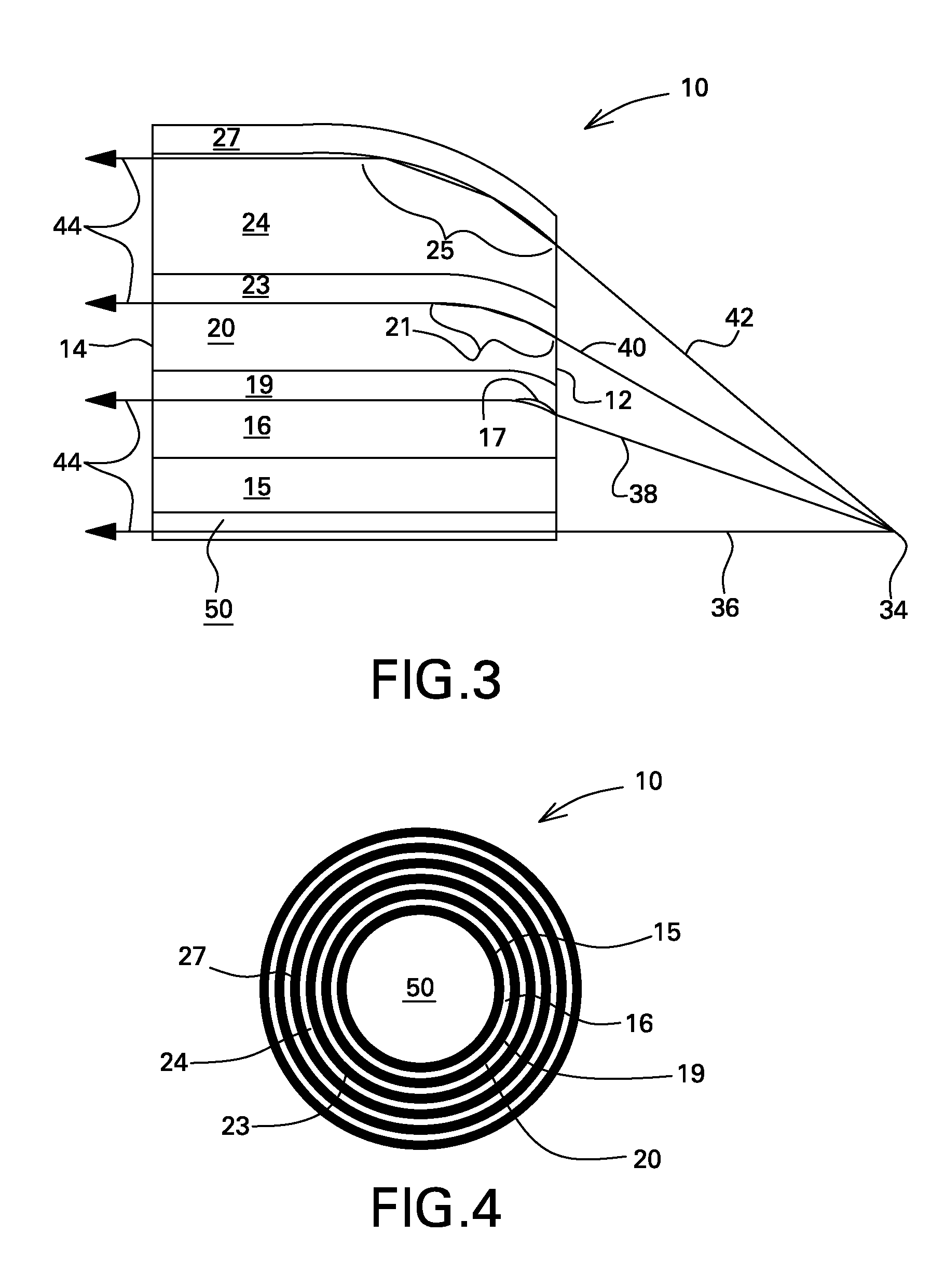
[0036]Referring now to FIGS. 2-5, there is shown a multilayer optic 10 including an input face 12 and an output face 1...


PUM


Abstract

A multi-energy imaging system and method for selectively generating high-energy X-rays and low-energy X-ray beams are described. A pair of optic devices are used, one optic device being formed to emit high X-ray energies and the other optic device being formed to emit low X-ray energies. A selective filtering mechanism is used to filter the high X-ray energies from the low X-ray energies. The optic devices have at least a first solid phase layer having a first index of refraction with a first photon transmission property and a second solid phase layer having a second index of refraction with a second photon transmission property. The first and second layers are conformal to each other.

Description

BACKGROUND[0001]The invention relates generally to optics, and more particularly to multilayer optic devices and methods for making the same.[0002]Numerous applications exist that require a focused beam of electromagnetic radiation. For example, energy dispersive X-ray diffraction (EDXRD) may be used to inspect checked airline baggage for the detection of explosive threats or other contraband. Such EDXRD systems may suffer from high false positives due to weak diffracted X-ray signals. The weakness of the X-ray signals may stem from a variety of origins. First, the polychromatic X-ray spectrum used in EDXRD is produced by the Bremsstrahlung part of the source spectrum, which is inherently low in intensity. Second, X-ray source collimation may eliminate more than 99.99 percent of the source X-rays incident on the baggage volume under analysis. Third, some of the materials being searched for, e.g., explosives, may not diffract strongly as they are amorphous. Fourth, the diffracting vo...

Claims


Application Information

Patent Timeline
Patent Type & Authority Applications(United States)
IPC IPC(8): H01J35/18G21K3/00
CPCB82Y10/00G21K1/062G21K1/10H01J2235/183G21K2201/064G21K2201/067H01J35/16G21K2201/061
Inventor HOPKINS, FORREST FRANKLEE, SUSANNE MADELINEEDIC, PETER MICHAEL
Owner GENERAL ELECTRIC CO
Why Eureka
Try Eureka