Method for high volume manufacturing of thin film batteries

a thin film battery, high-volume technology, applied in sustainable manufacturing/processing, non-aqueous electrolyte cells, flat cell grouping, etc., can solve the problems of reducing throughput, increasing the cost of ownership, limiting the substrate size and type, etc., to reduce costs, reduce costs, and reduce non-functional area , the effect of high volume and throughpu

Active Publication Date: 2009-06-11
APPLIED MATERIALS INC +1
View PDF8 Cites 79 Cited by
  • Summary
  • Abstract
  • Description
  • Claims
  • Application Information

AI Technical Summary

Benefits of technology

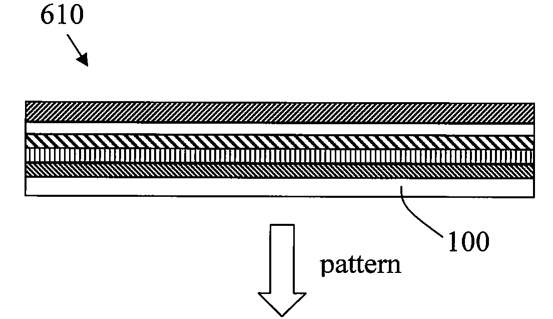
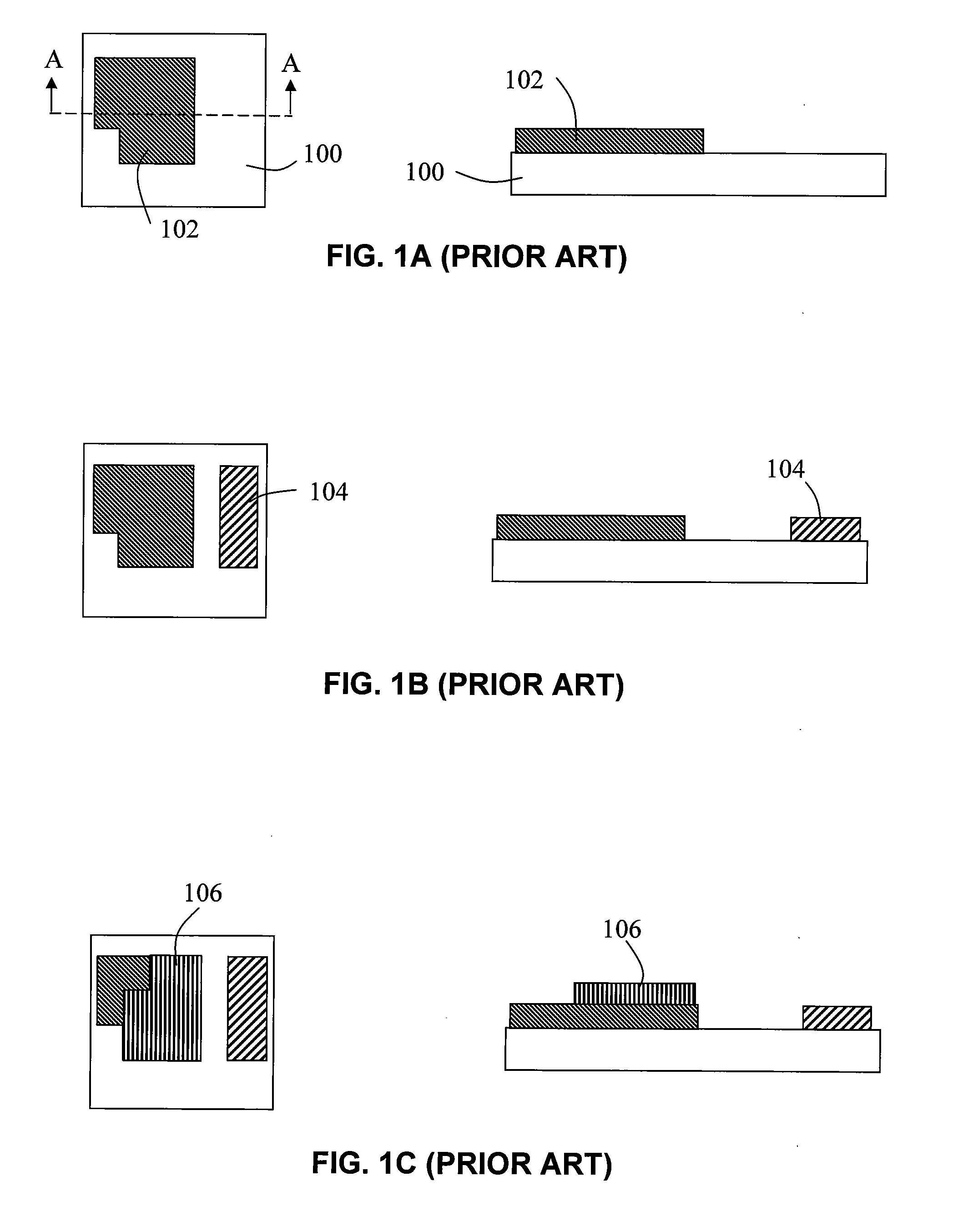
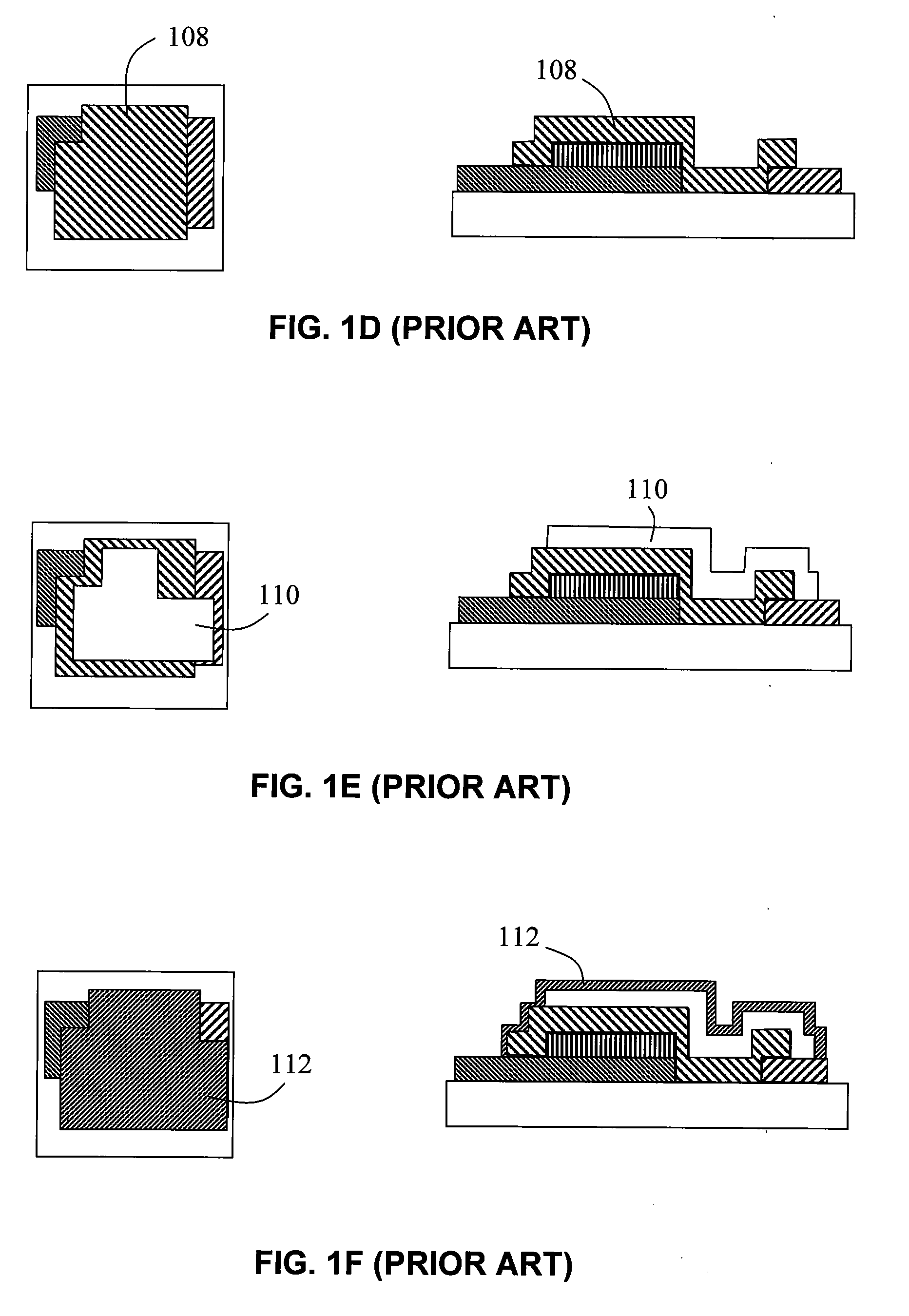
[0011]Concepts and methods of the invention allow the cost and complexity of TFB HVM to be reduced by eliminating and / or minimizing the use of physical (shadow) masks to enhance manufacturability of the products at high volume and throughput and the technique is easily adapted to large area substrates. This can significantly reduce the cost for broad market applicability as well as provide yield improvements. These and other advantages are achieved with the use of laser scribing or alternative maskless patterning techniques to meet certain or all of the patterning requirements. Alternative physical (shadow) maskless patterning techniques include mechanical sawing, water / solvent knifing, ion beam milling and multi-layer photolithography. As such, embodiments of the invention provide for the use of laser scribing, or other alternative maskless patterning techniques, anywhere during the manufacturing process as deemed appropriate and necessary for TFB manufacturability, yield and functionality. This includes a method where a single patterning is performed at the end of the deposition of all layers. Furthermore, embodiments of the invention provide methods which include multiple patterning, wherein each patterning addresses single or multiple stack layers, such that some physical (shadow) masking has been eliminated. If the physical masking is deemed necessary in some cases, then the disclosed concept can be implemented in conjunction with a minimum number of required physical masks. Preferably, for such processes wherein separate masking / patterning is necessary, laser scribing or alternative physical maskless patterning techniques would be used. Furthermore, the disclosed concept can be implemented with other physical maskless patterning techniques, like photolithographic patterning, in some cases where single, multiple or all layers are patterned simultaneously.
[0015]By following the disclosed concepts and resulting methods, many advantages in addition to high volume and throughput and reduced costs are achieved. For example, non-functional area is minimized or eliminated. Another is that the laser and other alternative methods allow flexibility in device patterning to accommodate end-market defined form factors, without having to create new expensive physical masks or reticles (for lithography). As another benefit, the anode current collector functions as the protective coating, eliminating or minimizing the need for complex multilayers or other schemes to package the device. An additional benefit is the positive impact to yield that will be realized.

Problems solved by technology

The traditional physical masking requirement leads to many disadvantages, especially related to HVM.
For example, the use of physical masking will (1) add significant capital investment requirement for HVM and large area scaling, (2) increase cost of ownership (consumable mask cost, cleaning, chemicals, etc.), (3) decrease throughput because of alignment requirements, and (4) limit the substrate size and type (rigid, semi-rigid, or flexible), and thereby, limit the scaling for economy and cost reduction.
More particularly, in HVM processes, the use of physical masks (ubiquitous for traditional and current state-of-the-art TFB fabrication technologies) will contribute to higher complexity and higher cost in manufacturing.
The complexity and cost result from the required fabrication of highly accurate masks and (automated) management systems for mask alignment and regeneration.
In addition, the cost results from the need for maintaining the masks as well as from throughput limitations by the added alignment steps.
The adaptation becomes increasingly more difficult and costly as the manufacturing is scaled to larger area substrates for improved throughput and economies of scale (i.e., high volume manufacturing).
Moreover, the scaling (to larger substrates) itself can be limited because of the limited availability and capability of the physical masks.
Another impact of the use of physical masking is the reduced utilization of a given substrate area, leading to non-optimal battery densities (charge, energy and power).
The consequence of this minimum non-overlap requirement is the loss of cathode area, leading to overall loss of capacity, energy and power content of the TFB (when everything else is the same).
And finally, processes that employ physical (shadow) masks typically suffer from particulate contamination, which ultimately impacts the yield.

Method used


Image

  • Method for high volume manufacturing of thin film batteries
  • Method for high volume manufacturing of thin film batteries
  • Method for high volume manufacturing of thin film batteries

Examples


Embodiment Construction

[0024]Embodiments of the present invention will now be described in detail with reference to the drawings, which are provided as illustrative examples so as to enable those skilled in the art to practice embodiments of the invention. Notably, the figures and examples below are not meant to limit the scope of the present invention to a single embodiment, but other embodiments are possible by way of interchange of some or all of the described or illustrated elements. Moreover, where certain elements of the present invention can be partially or fully implemented using known components, only those portions of such known components that are necessary to describe embodiments of the present invention will be discussed, and detailed descriptions of other portions of such known components will be omitted. In the present specification, an embodiment showing a singular component should not be considered limiting; rather, embodiments of the invention broadly encompass other variations including...


PUM

PropertyMeasurementUnit
thickaaaaaaaaaa
thickaaaaaaaaaa
thickaaaaaaaaaa

Abstract

Concepts and methods are provided to reduce the cost and complexity of thin film battery (TFB) high volume manufacturing by eliminating and / or minimizing the use of conventional physical (shadow) masks. Laser scribing and other alternative physical maskless patterning techniques meet certain or all of the patterning requirements. In one embodiment, a method of manufacturing thin film batteries comprises providing a substrate, depositing layers corresponding to a thin film battery structure on the substrate, the layers including, in order of deposition, a cathode, an electrolyte and an anode, wherein at least one of the deposited layers is unpatterned by a physical mask during deposition, depositing a protective coating, and scribing the layers and the protective coating. Further, the edges of the layers may be covered by an encapsulation layer. Furthermore, the layers may be deposited on two substrates and then laminated to form the thin film battery.

Description

CROSS-REFERENCE TO RELATED APPLICATIONS[0001]This application claims benefit of U.S. Provisional Patent Application Ser. No. 60 / 982,669, filed Oct. 25, 2007, which is herein incorporated by reference.FIELD OF THE INVENTION[0002]The present invention relates generally to thin film batteries, and more particularly to a method for fabricating thin film batteries that is low-cost and compatible with high-volume manufacturing.BACKGROUND OF THE INVENTION[0003]Solid state Thin Film Batteries (TFB) are known to exhibit several advantages over conventional battery technology such as superior form factors, cycle life, power capability and safety. However, there is a need for cost effective and high-volume manufacturing (HVM) compatible fabrication technologies to enable broad market applicability of TFBs.[0004]Past approaches to the patterning requirements for the TFB fabrication consisted of applying known methods of masking / patterning, such as photolithography and physical (shadow) masking....

Claims


Application Information

Patent Timeline
Patent Type & Authority Applications(United States)
IPC IPC(8): H01M6/18B05D5/12
CPCH01M6/40H01M10/0436H01M2300/0068H01M10/0585H01M10/052Y02E60/10Y02P70/50H01M4/0426H01M4/139
Inventor KWAK, BYUNG SUNGKRISHNA, NETY M.EISENBELSER, KURTDAUKSHER, WILLIAM J.CANDELARIA, JON
Owner APPLIED MATERIALS INC
Why Eureka
Try Eureka