Cooling fan arrangement at a vehicle

a technology for radiator fans and vehicles, which is applied in the direction of mechanical equipment, machines/engines, transportation and packaging, etc., can solve the problems that the air flow generated by the first radiator fan is not sufficient to provide the necessary achieve increase the effect of forced air flow and uniform cooling of the medium

Active Publication Date: 2009-06-25
SCANIA CV AB
View PDF22 Cites 31 Cited by
  • Summary
  • Abstract
  • Description
  • Claims
  • Application Information

AI Technical Summary

Benefits of technology

[0009]According to another preferred embodiment of the invention, the first radiator fan and the extra radiator fan are so situated relative to one another that they provide substantially parallel air flows through at least partly different regions of the cooling element. Placing the extra radiator fan beside the first radiator fan with respect to the intended air flow direction through the cooling element will result in a broader air flow through the cooling element when both of the radiator fans are activated. Suitable positioning of the extra radiator fan relative to the first radiator fan will make it possible substantially to provide the cooling element with a more homogeneous cooling air flow resulting in uniform cooling of the medium in the cooling element. With advantage, the radiator arrangement comprises a control unit adapted to activating the extra radiator fan on the basis of information from at least one sensor which detects a parameter related to the temperature of the medium when it leaves the cooling element. If the control unit receives information from the sensor which indicates that the medium is at too high a temperature when it leaves the cooling element, the control unit will find that the cooling of the medium in the cooling element is insufficient. The control unit will thereupon activate the extra radiator fan so that there is increased forced air flow through the cooling element and hence increased cooling of the medium in the cooling element. When the first radiator fan receives information from the sensor that the temperature of the medium has dropped to an acceptable temperature level, it will switch off the extra radiator fan.
[0010]According to another preferred embodiment of the invention, said cooling element is a radiator intended to cool a coolant in a cooling system for cooling the combustion engine. Where two or more cooling elements are used in a vehicle, the radiator for the coolant is usually situated downstream from other cooling elements with respect to the direction of the cooling air flow, since the coolant need not normally be cooled to as low a temperature as the media in other cooling elements. Thus the coolant in the radiator will be cooled by an air flow which is at a higher temperature than the surroundings. This increases the risk that the coolant may not be subject to a necessary cooling in the radiator. It is therefore particularly advantageous to use an extra radiator fan according to the present invention for providing an increased cooling air flow in cases where the radiator for the coolant is situated downstream from other cooling elements. Other cooling elements such as, for example, a charge air cooler may need an increased cooling air flow in operating situations where air is subject to great compression in a turbo unit. It is important that the air in a charge air cooler be cooled to a relatively low temperature if the combustion engine is to achieve high performance.
[0011]According to another preferred embodiment of the invention, said cooling elements, the first radiator fan and the extra radiator fan are fitted in a region situated at a front portion of the vehicle. In this region commonly used as the location for cooling elements, a natural air flow through the cooling element is also provided by the vehicle's motion, thereby also helping to cool the medium in the cooling element.

Problems solved by technology

In situations where, for example, there is a high surrounding air temperature or the medium in the cooling element is at a high temperature, there is always risk that the existing air flow generated by the first radiator fan will not be sufficient to provide necessary cooling of the medium.
In this case, cooling the medium will not entail any problems in operating situations where the combustion engine is idling or running at low speed, which may be a disadvantage of using a first radiator fan powered by the combustion engine.

Method used


Image

  • Cooling fan arrangement at a vehicle
  • Cooling fan arrangement at a vehicle
  • Cooling fan arrangement at a vehicle

Examples


Embodiment Construction

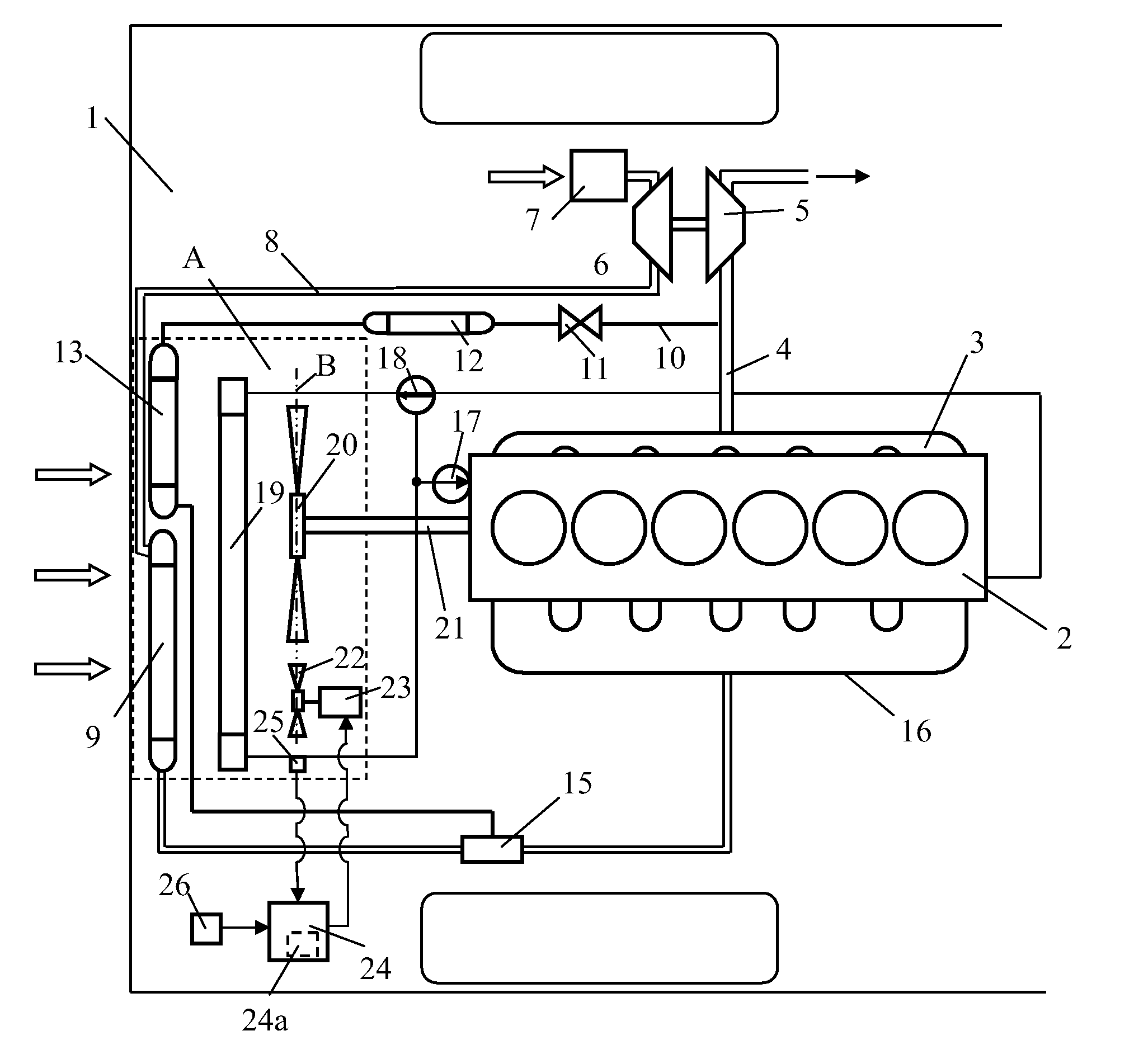
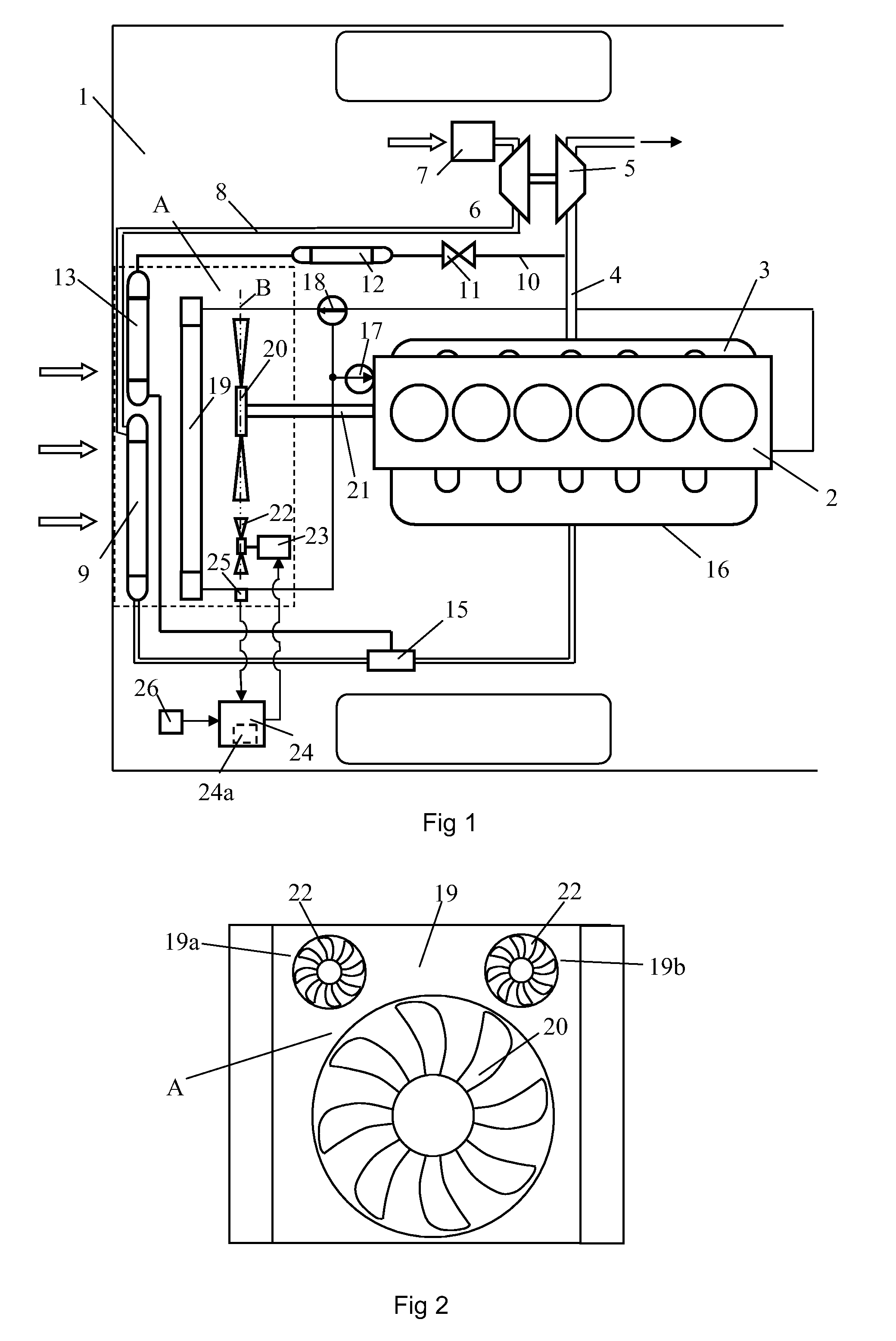
[0016]FIG. 1 depicts a vehicle 1 powered by a supercharged combustion engine 2. The vehicle 1 may be a heavy vehicle powered by a supercharged diesel engine. The exhaust gases from the cylinders of the combustion engine 2 are led via an exhaust manifold 3 to an exhaust line 4. The exhaust gases in the exhaust line 4, which will be at above atmospheric pressure, are led to a turbine 5 of a turbo unit. The turbine 5 is thereby provided with driving force which is transmitted, via a connection, to a compressor 6. The compressor 6 thereupon compresses air which is led via an air filter 7 into an inlet line 8. A charge air cooler 9 is arranged in the inlet line 8. The purpose of the charge air cooler 9 is to cool the compressed air before it is led to the combustion engine 2.

[0017]The combustion engine 2 is provided with an EGR (Exhaust Gas Recirculation) system for recirculation of exhaust gases. Adding exhaust gases to the compressed air which is led to the engine's cylinders lowers th...


PUM


Abstract

A radiator fan arrangement for a vehicle which is powered by a combustion engine. The radiator fan arrangement includes at least one cooling element for cooling a medium, and a first radiator fan for continuously generating a forced air flow through at least one first region of the cooling element in order to cool the medium during operation of the combustion engine. The radiator fan arrangement also includes at least one extra radiator fan for being activated to generate an increased air flow through at least one second region of said cooling element in situations where the first radiator fan cannot provide sufficient air flow to cool as necessary the medium in the cooling element.

Description

BACKGROUND TO THE INVENTION, AND STATE OF THE ART[0001]The present invention relates to a radiator fan arrangement for a vehicle according to the preamble of claim 1.[0002]A vehicle powered by a combustion engine usually comprises a radiator for cooling the coolant which cools the combustion engine. A radiator fan is usually arranged close to the radiator in order to provide a forced air flow through the radiator with the object of cooling the coolant. Conventional radiator fans are usually powered by the combustion engine via a permanent mechanical connection. The magnitude of the air flow which the radiator fan generates through the radiator will thus vary with the engine's speed. Many heavy vehicles are powered by supercharged combustion engines. A charge air cooler is used for cooling the supercharged air before it is led to the combustion engine. A charge air cooler is usually situated in front of the ordinary radiator at the front portion of the vehicle. In some cases a conden...

Claims


Application Information

Patent Timeline
Patent Type & Authority Applications(United States)
IPC IPC(8): F01P7/02
CPCB60K11/04F01P5/02F01P2025/36F01P2003/185F01P2005/025F01P7/048
Inventor KARDOS, ZOLTAN
Owner SCANIA CV AB
Why Eureka
Try Eureka