Liquid crystal projector and image reproducing device

a liquid crystal projector and image reproducing technology, which is applied in the field of liquid crystal projectors and image reproducing devices, can solve the problems of difficult to include the projector in a small device such as a portable telephone terminal, and the display area of liquid crystal display panels is too large, so as to improve the light use efficiency and improve the image contrast

Active Publication Date: 2009-06-25
SONY CORP
View PDF9 Cites 18 Cited by
  • Summary
  • Abstract
  • Description
  • Claims
  • Application Information

AI Technical Summary

Benefits of technology

[0012]Moreover, as is pointed out in Japanese Patent Laid-open No. 2005-116799, the angle of divergence of light emitted by the LED is large. When this is used as a light source for a projector, Etendue is too large as compared with the display area of a liquid crystal display panel. As a result, light use efficiency is lowered.
[0023]As described above, according to the present invention, it is possible to miniaturize the projector as a whole to such a degree that the projector can be included in a small device such as a portable telephone terminal or the like, and to achieve an improvement in light use efficiency, which is essential as the projector, and an improvement in image contrast.

Problems solved by technology

It is difficult to include the projector in a small device such as a portable telephone terminal or the like.
When this is used as a light source for a projector, Etendue is too large as compared with the display area of a liquid crystal display panel.

Method used


Image

  • Liquid crystal projector and image reproducing device
  • Liquid crystal projector and image reproducing device
  • Liquid crystal projector and image reproducing device

Examples


first embodiment

1. First Embodiment

(Single-Panel Type): FIGS. 1 to 13

[0042]A case of a single-panel system using one liquid crystal display panel (liquid crystal light valve) for three colors of red, green, and blue will be shown as a first embodiment.

1-1. First Example of Basic Configuration

(Case of Using Diffractive Optical Element): FIGS. 1 to 5

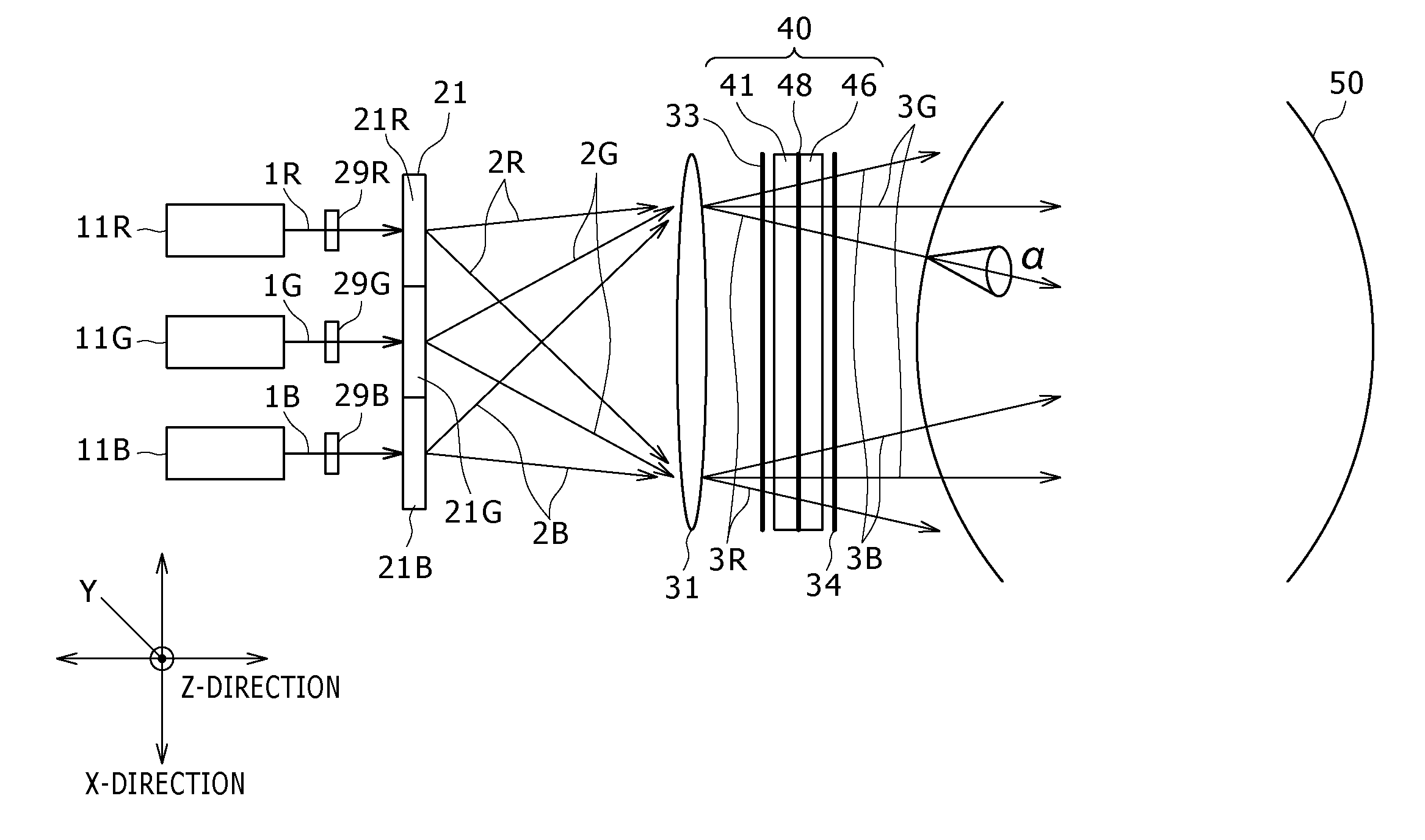
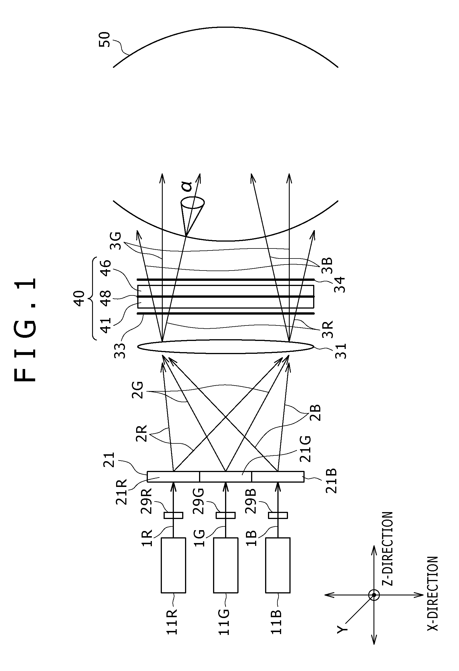
[0043]FIG. 1 illustrates a case of using a diffractive optical element as a light beam diffusing and shaping optical element, as a first example of basic configuration of a single-panel type liquid crystal projector.

[0044]In order to clarify directions, an X-direction, a Y-direction, and a Z-direction are defined as shown in the figures. The Y-direction is a direction perpendicular to a paper plane in FIG. 1.

[0045]In this example, as a light source, a red laser 11R, a green laser 11G, and a blue laser 11B are arranged and disposed in the X-direction.

[0046]A semiconductor laser is used as each of the red laser 11R and the blue laser 11B. For example, an In...

concrete example

[0080]In the example of FIG. 1, as an example, a constitution is formed as follows.

[0081]An InAlGaP base semiconductor laser having an oscillation wavelength of 635 nm to 640 nm is used as the red laser 11R. A GaN base semiconductor laser having an oscillation wavelength of 445 nm is used as the blue laser 11B. Each has an output of 100 mW, has a light divergence angle of 30 degrees (FWHM) in a vertical direction, has a light divergence angle of 10 degrees in a horizontal direction, has a single mode as a transverse mode, and has a multi-mode as a longitudinal mode.

[0082]A solid-state laser that is pumped by an 808-nm semiconductor laser, has an oscillation wavelength of 532 nm, and uses a YVO4+KTP second harmonic is used as the green laser 11G. An output is 100 mW, a transverse mode is a single mode, and a longitudinal mode is a multi-mode.

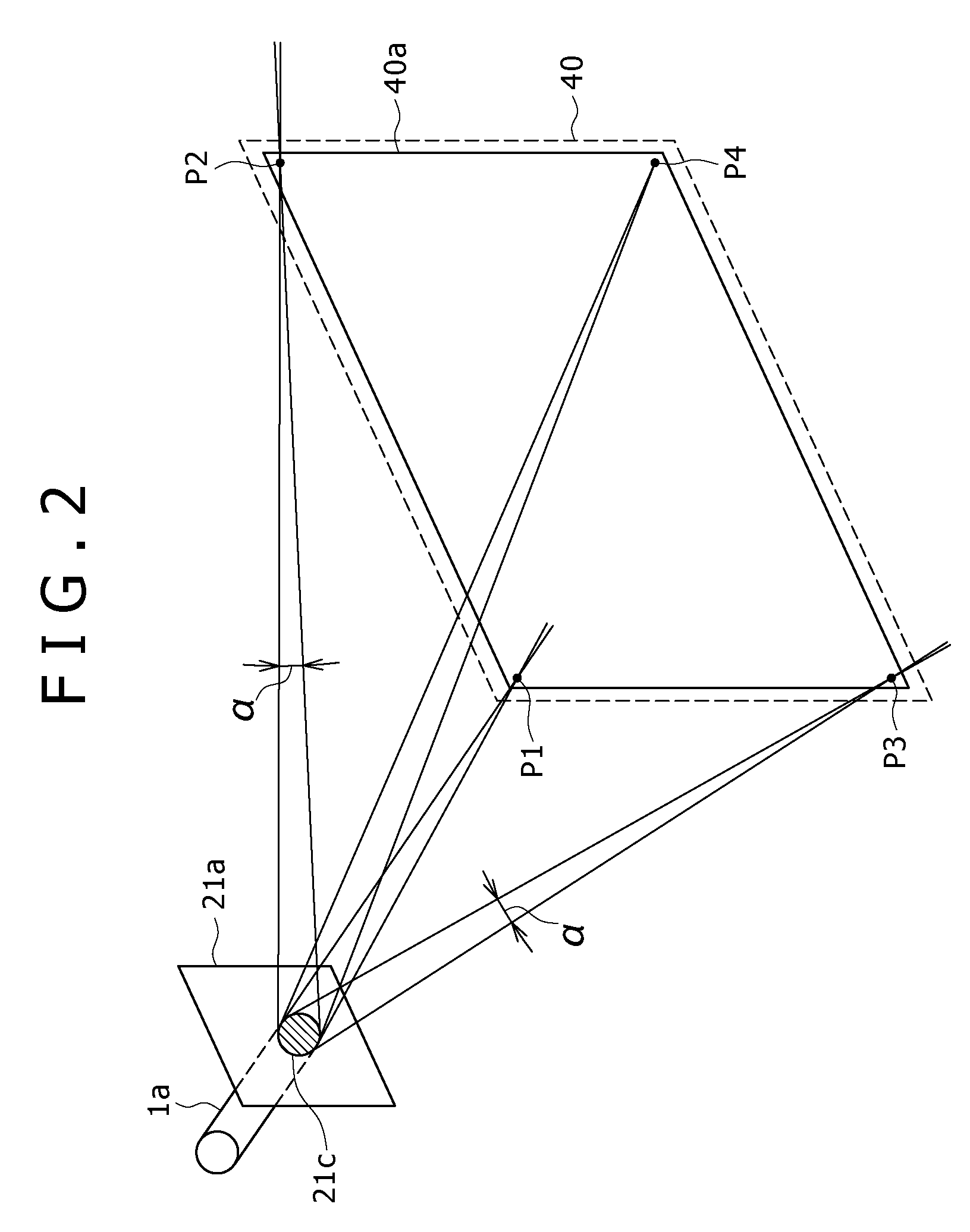
[0083]Parallelism between the laser light beams 1R, 1G, and 1B is important in controlling angles of incidence on the field lens 31 of the laser...

second embodiment

2. Second Embodiment

(Two-Panel Type): FIGS. 14 to 16

[0135]A case of a two-panel system using two liquid crystal display panels (liquid crystal light valves) for three colors of red, green, and blue will be shown as a second embodiment.

2-1. First Example: FIG. 14 and FIG. 15

[0136]FIG. 14 shows an example of a two-panel type liquid crystal projector.

[0137]In this example, as a light source, a red laser 11R and a blue laser 11B are disposed in proximity to each other, and a green laser 11G is disposed at a different position. The red laser 11R and the blue laser 11B are each a semiconductor laser as described above. The green laser 11G is a DPSS laser as described above.

[0138]Though not shown in FIG. 14, it is desirable that also in this example, as in the example of FIG. 9, a collimation optical system for bringing the sectional shape of a laser light beam emitted from each of the red laser 11R and the blue laser 11B close to a circular shape be provided for the red laser 11R and the ...


PUM

PropertyMeasurementUnit
lengthaaaaaaaaaa
oscillation wavelengthaaaaaaaaaa

Abstract

In order to miniaturize a projector as a whole to such a degree that the projector can be included in a small device such as a portable telephone terminal or the like, a red laser light beam (1R) is diffused and shaped by a diffractive optical element (21R) for red, a green laser light beam (1G) is diffused and shaped by a diffractive optical element (21G) for green, and a blue laser light beam (1B) is diffused and shaped by a diffractive optical element (21B) for blue, so as to be each spread over an entire display area of a liquid crystal display panel (40) and be incident on corresponding pixels of a liquid crystal layer (48). The diffused and shaped laser light beams (2R, 2G, and 2B) are made incident on the liquid crystal display panel (40) via a field lens (31). In the liquid crystal display panel (40), red, green, and blue pixels are formed, and a microlens array is formed in an incidence side substrate (41). The liquid crystal display panel (40) distributes and condenses the laser light of the colors by microlenses, and makes the laser light incident on the corresponding pixels. Refraction type optical elements can be used in place of the diffractive optical elements.

Description

TECHNICAL FIELD[0001]The present invention relates to a projector (projection type display device) using a liquid crystal display panel (liquid crystal display device) as a light valve, and an image reproducing device such as a portable telephone terminal, a digital camera, a video camera, a personal computer, a game machine, a toy and the like.BACKGROUND ART[0002]A projector is conventionally and generally regarded as a thing to be installed and used within a house or the like. As disclosed in Japanese Patent Laid-open No. 63-118125, Japanese Patent Laid-open No. Hei 4-60538, and the like, a lamp such as a metal halide lamp, a high pressure mercury lamp, a xenon lamp or the like is used as a light source.[0003]However, when a lamp is used as a light source, there are for example problems in that (a) the aperture of a light source unit is increased, resulting in a larger size of the projector as a whole, (b) the light source unit generates a large amount of heat and thus requires a ...

Claims


Application Information

Patent Timeline
Patent Type & Authority Applications(United States)
IPC IPC(8): G02F1/13357
CPCH04N9/3108H04N9/3161H04N9/3173H04N9/3197G03B33/12G03B21/208G03B21/006G03B21/2033G03B33/06G03B21/2013G03B21/00G03B21/14
Inventor KAISE, KIKUO
Owner SONY CORP
Why Eureka
Try Eureka