
Phase Contrast Electron Microscope Device

a phase contrast and electron microscope technology, applied in the direction of instruments, nuclear engineering, material analysis using wave/particle radiation, etc., can solve the problems of reducing the resolution, reducing the signal intensity caused by the electron beam, and induced image distortion caused by the electric charge or signal intensity decrease caused by the loss of electron beams, etc., to achieve small image distortions resulting from defocusing and improve image quality in the depth direction

Inactive Publication Date: 2009-07-02
INTER UNIV RES INST NAT INST OF NATURAL SCI +1
View PDF3 Cites 22 Cited by
  • Summary
  • Abstract
  • Description
  • Claims
  • Application Information

AI Technical Summary

Benefits of technology

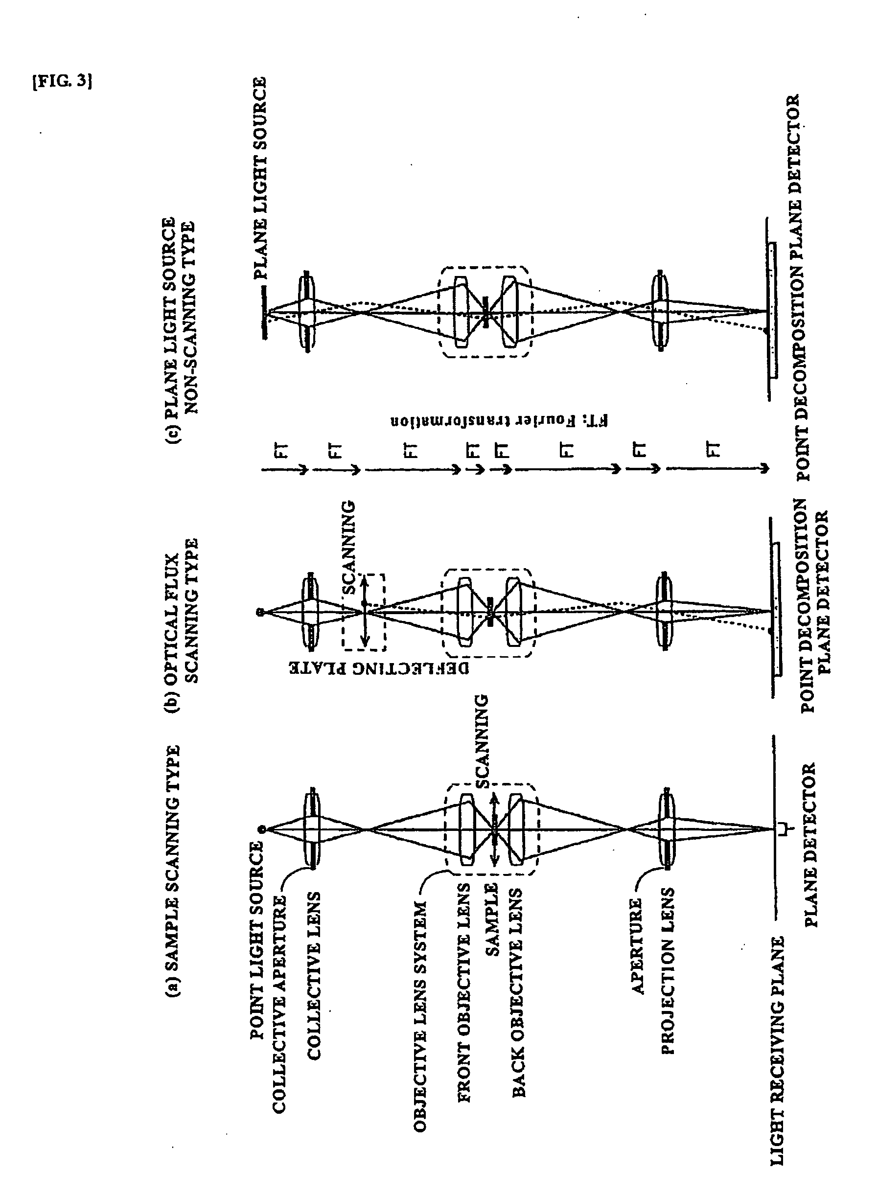
[0032]In accordance with the present invention that has the above-described features, it is possible to realize not only a conventional phase contrast electron microscope in which a phase plate is disposed behind the sample (on the projection lens side), but also a phase contrast electron microscope in which a phase plate is disposed in front of the sample (on the collective lens side). As a result, composition spatial filters of various types that have heretofore been unknown can be designed and an electron microscope technology that can resolved both the problem of the phase plate being electrically charged and the problem of electron beam loss can be established.
[0037]2. In the case of the phase contrast method, the phase plate can be disposed in front of the sample. Therefore, electron beam loss can be avoided and contrast can be increased without decreasing the resolution.
[0040]5. A halo on the image circumference that is a crucial drawback of the phase contrast method, is eliminated.
[0043]8. Image distortions resulting from defocusing are small. Therefore, image quality in the depth direction is improved over that attained when TEM or STEM is used in tomographic observations that require tilted samples.

Problems solved by technology

On the other hand, in the conventional phase contrast electron microscopes (Japanese Patent Applications Laid-open Nos. 2001-273866, 2002-237272, and 2003-100249 and Japanese Patent Applications Nos. 2004-351902 and 2005-321402), because a phase plate is introduced behind a sample, the trajectory of electron beam carrying the image information is disturbed and image distortions caused by electric charging or signal intensity decrease caused by electron beam loss are induced.
Among these problems, the distortion of image caused by electric charging has been resolved (Japanese Application No. 2004-351902), but the decrease in signal intensity caused by electron beam is difficult to prevent.
At the low-frequency side, the increase in contrast can be realized because the decrease is compensated by the properties of phase contrast method, but the decrease in signal intensity at the high-frequency side is not compensated and leads to the decrease in resolution.

Method used


Image

  • Phase Contrast Electron Microscope Device
  • Phase Contrast Electron Microscope Device
  • Phase Contrast Electron Microscope Device

Examples


Embodiment Construction

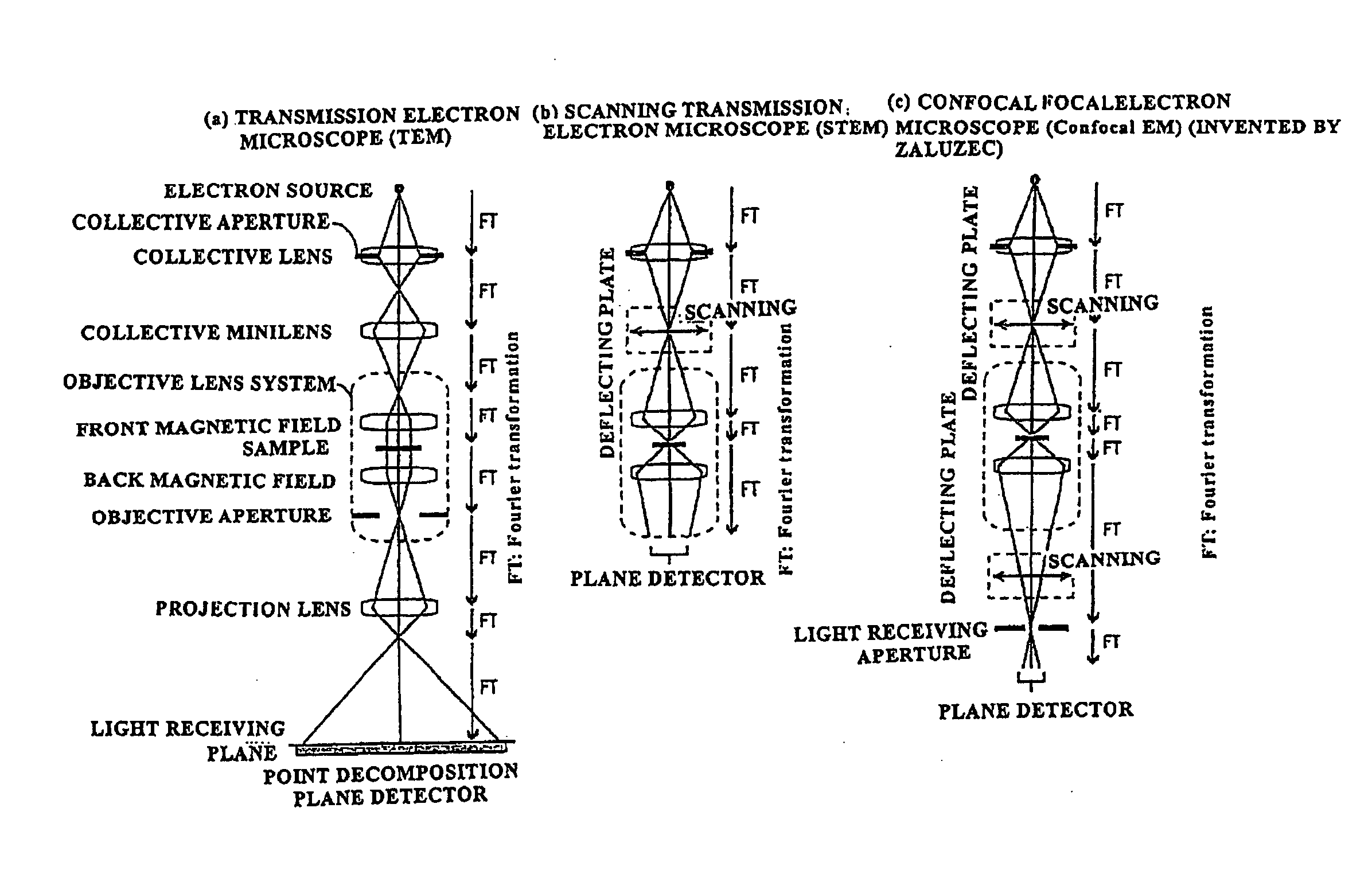
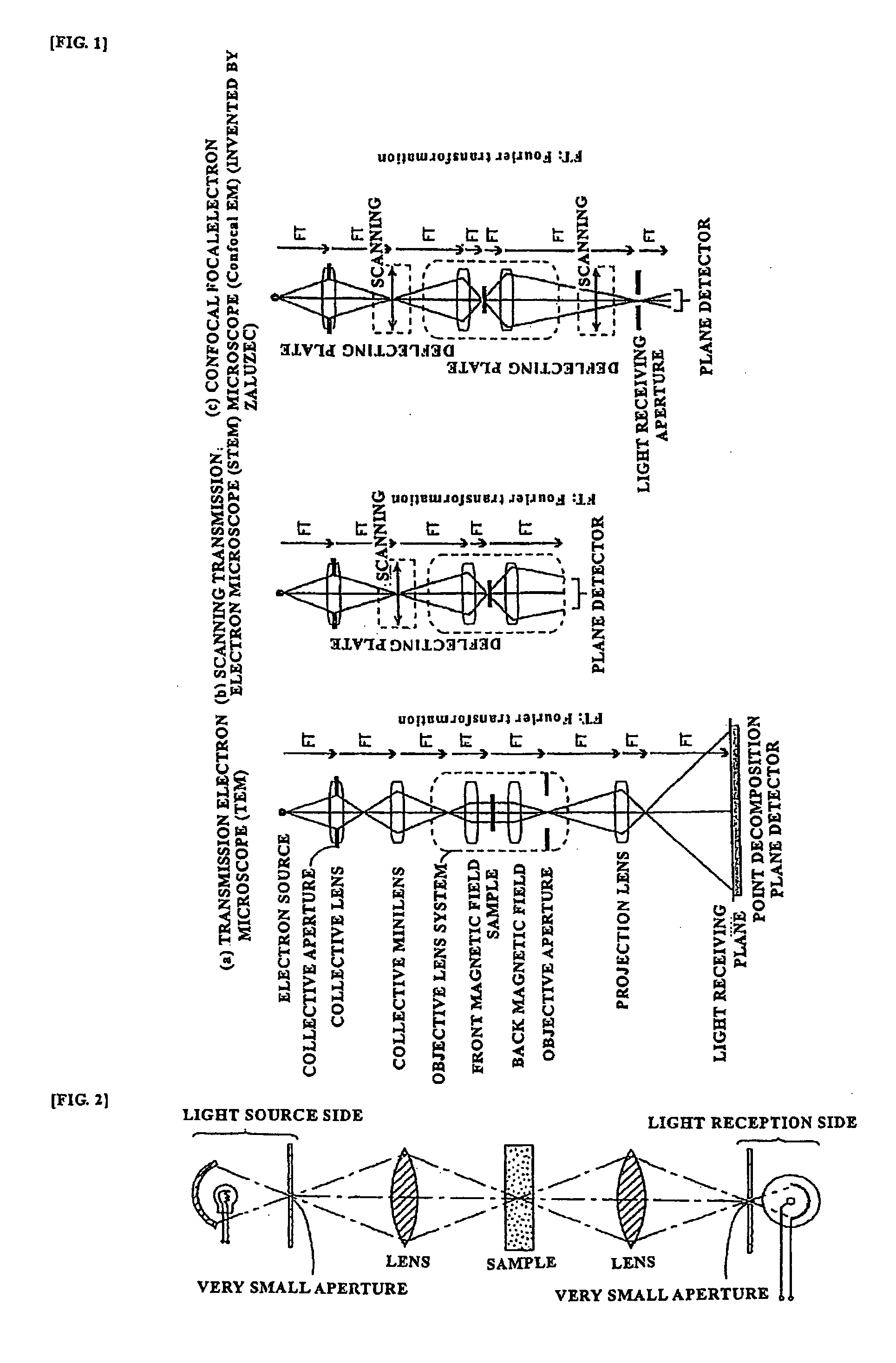
[0063]i) Conventional Electron Microscope

[0064]First, a conventional electron microscope will be explained using FIGS. 1(a), (b), (c). In FIGS. 1(b), (c), no reference symbols are assigned to the structural elements identical to those of FIG. 1(a).

[0065]In a TEM, as shown by way of example in FIG. 1(a), a point light source (point electron source) is converted into a parallel beam (parallel electron wave) by a lens system to irradiate a sample, and the light (electron wave) that has been transmitted through the sample is expanded by a lens system, and caused to fall on a light receiving plate of a point decomposition plane detector such as a photographic detector or a CCD (Charge Coupled Device) camera to produce an image. A parallel light containing scattered electrons from the sample is once collected at an aperture stop and then the so-called image is produced on the entire light receiving plane by a projection lens. Therefore, the image pickup is performed by opening a shutter, ...


PUM

PropertyMeasurementUnit
thicknessaaaaaaaaaa
electron microscopeaaaaaaaaaa
magnetic fieldaaaaaaaaaa

Abstract

A confocal method in which a sample is disposed in the center, a collective lens and a front objective lens are disposed on the incident side, and a back objective lens and a projection lens are disposed symmetrically on the outgoing side is so configured that a spatial filter can be inserted in front of the sample and behind it. As a result, the advantage of the confocal method, which is in the possibility of disposing a spatial filter in front of the sample, is realized and the disadvantages of the conventional transmission phase contrast electron microscope (halo, electron beam loss) are eliminated, thereby providing a phase contrast electron microscope device that enables the establishment of an electron microscopy technology that makes it possible to view of a wide range of materials from material science to life science in a non-dyed state with a high contrast and a high resolution.

Description

TECHNICAL FIELD[0001]The present invention relates to a phase contrast electron microscope device.BACKGROUND ART[0002]An electron microscope, which is by its nature a paraxial optical system with a large focal depth, is not incompatible with a confocal method aimed at the decrease in focal depth. For this reason, the confocal microscope of Zaluzec (see U.S. Pat. No. 6,548,810 B2, “Scanning Confocal Electron Microscope”, S. P. Frigo, Z. H. Levine and N. J. Zaluzec, “Submicron Imaging of Buried Integrated Circuit Structures Using Scanning Confocal Electron Microscope”, Appl. Phys. Lett. 81 (2002) 2112-2114) is not applied to regions requiring high resolution, but only to thick materials that cannot be handled by the usual electron microscopes.[0003]On the other hand, in the conventional phase contrast electron microscopes (Japanese Patent Applications Laid-open Nos. 2001-273866, 2002-237272, and 2003-100249 and Japanese Patent Applications Nos. 2004-351902 and 2005-321402), because a ...

Claims


Application Information

Patent Timeline
Patent Type & Authority Applications(United States)
IPC IPC(8): G21K5/10G01N23/00
CPCH01J37/04H01J37/26H01J2237/2802H01J2237/2614H01J2237/0492
Inventor NAGAYAMA, KUNIAKI
Owner INTER UNIV RES INST NAT INST OF NATURAL SCI
Learn More