Method and control device for monitoring and limiting the torque in a drive train of a road motor vehicle

Inactive Publication Date: 2009-07-02
ROBERT BOSCH GMBH
View PDF16 Cites 17 Cited by
  • Summary
  • Abstract
  • Description
  • Claims
  • Application Information

AI Technical Summary

Benefits of technology

[0009]The following advantages result in comparison with current methods and devices for monitoring the torques of the drives: In the known method, the actual value of the current torque was compared to a permissible value. If the permissible value is exceeded, a time counter was activated. If the permissible value was undershot, the time counter was reset. If the value of the time counter exceeded a threshold, an error reaction was triggered. The extent of the exceedance was not evaluated. In a real driving situation, however, a high exceedance has a more critical effect than only a slight exceedance.
[0010]In contrast, the exemplary embodiments and/or exemplary methods of the present invention has the advantage that exceedances are recorded in quantitative terms as well and, by the sum operation, are also taken into account in quantitative terms in the decision as to whether or not a fault reaction is to be triggered. Furthermore, the summation (or integration) also provides a value that has a more direct relevance to the effect of the exceedance on the vehicle: A quantitatively greater exceedance causes greater acceleration than only an only smaller exceedance. In the invention, the fault reaction in the case of the greater exceedance is triggered earlier than in the case of the

Problems solved by technology

If the value of the time counter exceeded a

Method used


Image

  • Method and control device for monitoring and limiting the torque in a drive train of a road motor vehicle
  • Method and control device for monitoring and limiting the torque in a drive train of a road motor vehicle
  • Method and control device for monitoring and limiting the torque in a drive train of a road motor vehicle

Examples


Embodiment Construction

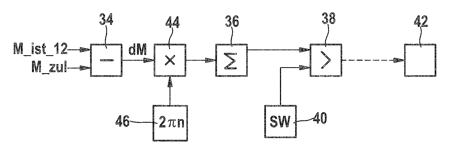
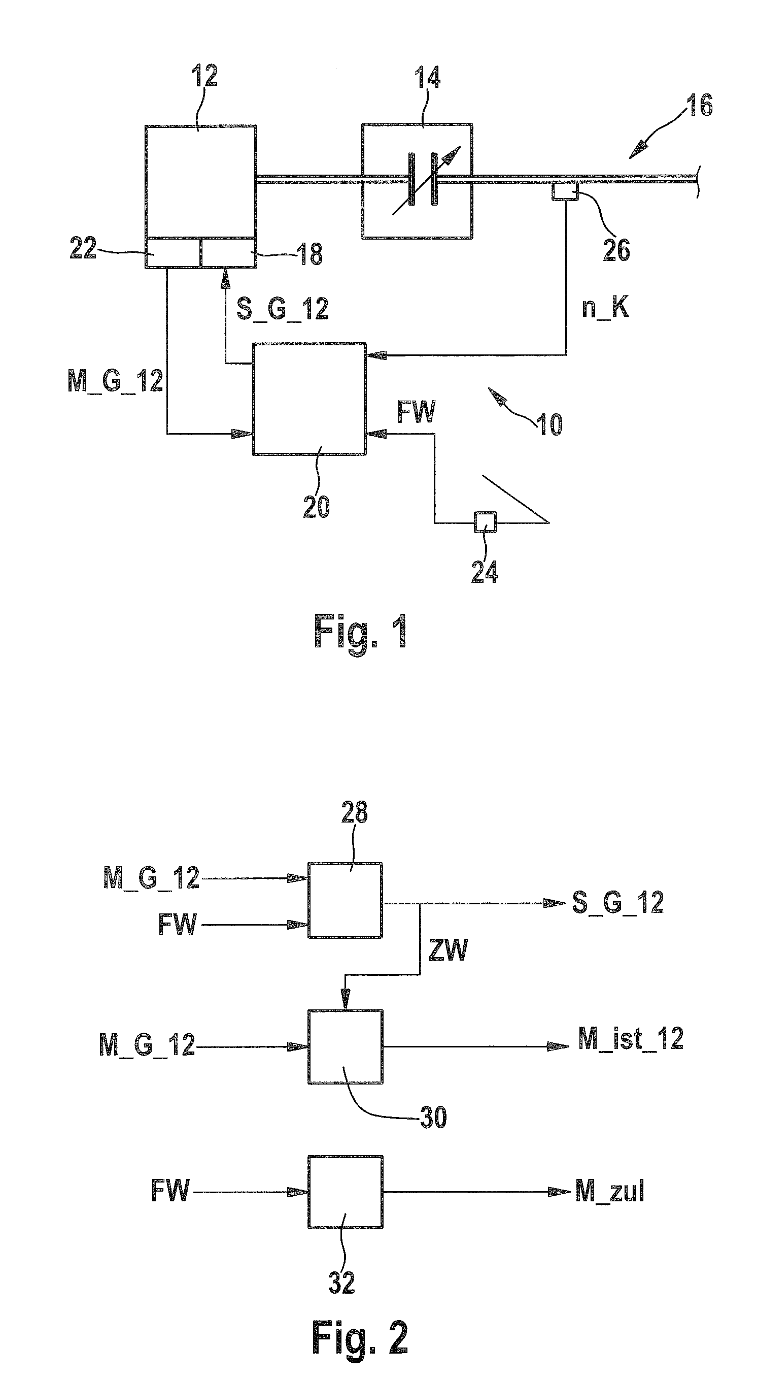
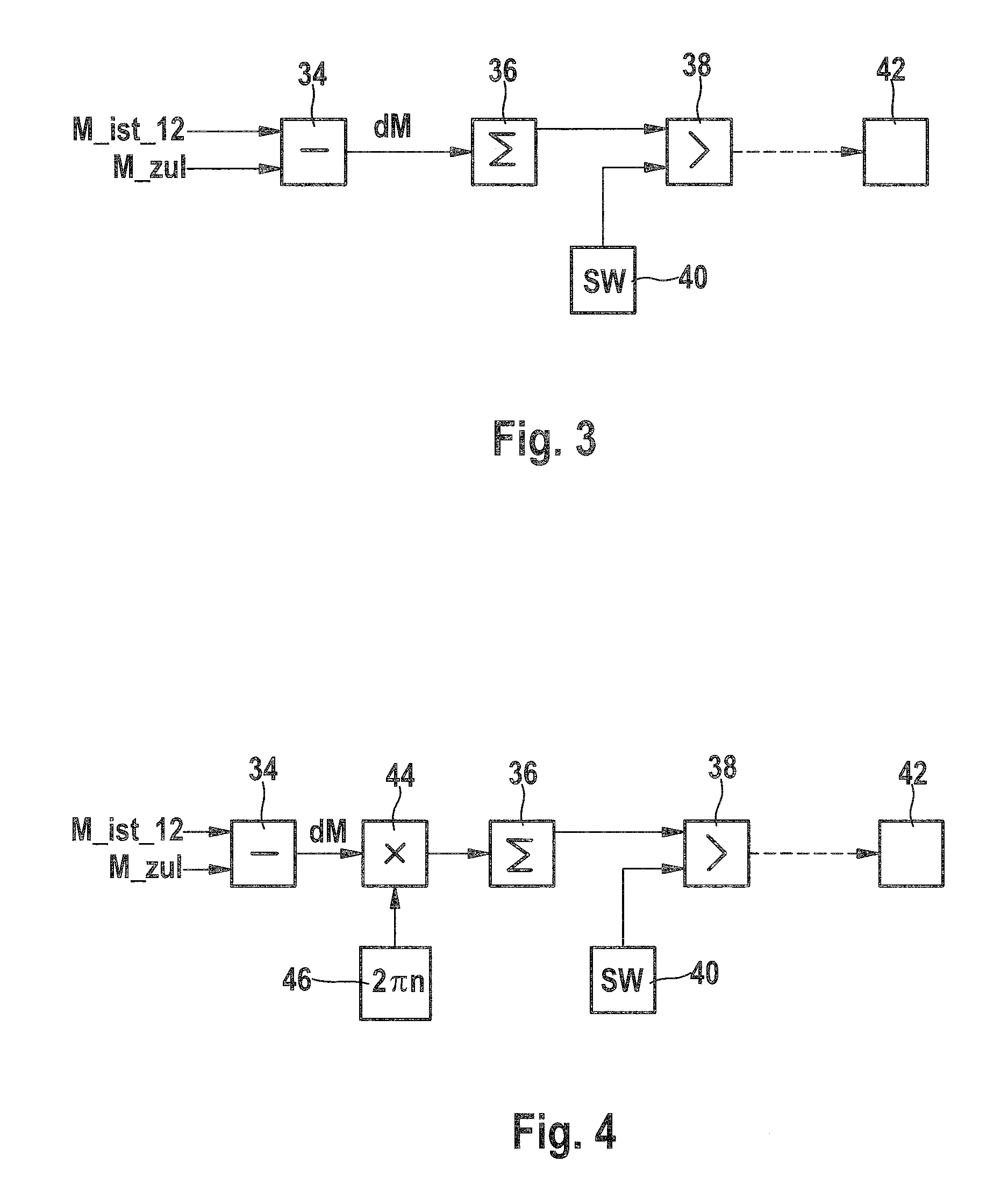
[0023]In detail, FIG. 1 shows a drive train 10 of a road motor vehicle together with a control of drive train 10. Drive train 10 in particular has a combustion engine 12, which is coupled to remainder 16 of the drive train via a clutch 14. Clutch 14 may be a friction clutch actuated automatically or by a driver, or a fluid clutch. Remainder 16 of drive train 10 represents additional elements usually provided for the torque transmission between the wheels and drive of the road motor vehicle, such as gear trains and shafts.

[0024]In the subject matter of FIG. 1, the drive torque is generated solely by combustion engine 12. To control its torque output, combustion engine 12 is equipped with final control elements 18 by which a charge of the combustion chambers of combustion engine 12 and / or the quality of the charge, i.e., a mixture ratio of fuel and air, for example, and / or the time sequence of the combustion are / is able to be controlled or influenced, for instance by shifting the mome...


PUM


Abstract

A method for monitoring and limiting the output or the torque of a drive motor in a drive train of a road motor vehicle, including the steps of: determining a permissible maximum value of the output or the torque as a function of a signal from a driver input sensor; determining an actual value of the output or the torque, and comparing the actual value to the maximum value and triggering a measure that limits the output or the torque as a function of the comparison result. The method is characterized by the repeated formation of a difference from the actual value and the maximum value, formation of a sum of values of a function of the difference, comparison of a value of the sum to a threshold value, and initiation of the measures if the value of the sum is greater than the threshold value. An independent claim is directed to a control device, which is programmed to implement the method.

Description

FIELD OF THE INVENTION[0001]The present invention relates to a method and control device for monitoring and limiting the torque in a drive train of a road motor vehicle.BACKGROUND INFORMATION[0002]A method and a control device of this type are both discussed in DE 195 36 038 A1.[0003]In modern combustion engines, performance-determinative actuators such as a throttle valve are no longer mechanically coupled to a driver-input sensor. Nowadays, a driver-input sensor typically converts a torque request from the driver into an electric signal, from which the control device determines one or a plurality of actuating variables for one or a plurality of performance-regulating final control elements. Malfunctions in the signal-processing chain between the driver-input sensor and the final control elements can therefore induce the combustion engine to generate more torque than the driver desired. To prevent this, in the known subject matter a permissible maximum value of the power output or ...

Claims


Application Information

Patent Timeline
IPC IPC(8): H02P6/08
CPCF02D41/22Y02T10/40F02D2250/26F02D2200/1004B60W50/038B60W10/02B60W10/06B60W10/08B60W20/00B60W30/184F02D41/022F02D41/1497B60W2510/0638B60W2510/0657B60W2510/0666B60W2540/10B60W2710/0666B60W2710/0677F02D2200/602B60W20/50Y02T10/62
Inventor GWINNER, ROBERT
Owner ROBERT BOSCH GMBH
Why Eureka
Try Eureka