Magnetic memory and method for writing to magnetic memory

a magnetic memory and random access technology, applied in information storage, static storage, digital storage, etc., can solve the problems of low cost structure of alternating-current oscillators, difficulty in further reducing this value in the future, and small maximum output of about 1 w, etc., to achieve small write current and low power consumption

Inactive Publication Date: 2009-07-02
HITACHI LTD
View PDF4 Cites 16 Cited by
  • Summary
  • Abstract
  • Description
  • Claims
  • Application Information

AI Technical Summary

Benefits of technology

[0019]The present invention can provide a magnetic random access memory having sma...

Problems solved by technology

However, the following problems exist in the TMR type MRAM employing the conventional spin torque magnetization reversal.
However, it is considered to be very difficult to further reduce this value in the future while ensuring thermal stability which is important for a nonvolatile memory.
Moreover, the spin torque oscillator illustrated in FIG. 2 has a problem in that its maximum output is a...

Method used


Image

  • Magnetic memory and method for writing to magnetic memory
  • Magnetic memory and method for writing to magnetic memory
  • Magnetic memory and method for writing to magnetic memory

Examples


example 1

Example in Which All of the Three Magnetoresistance Effect Elements are a TMR Element

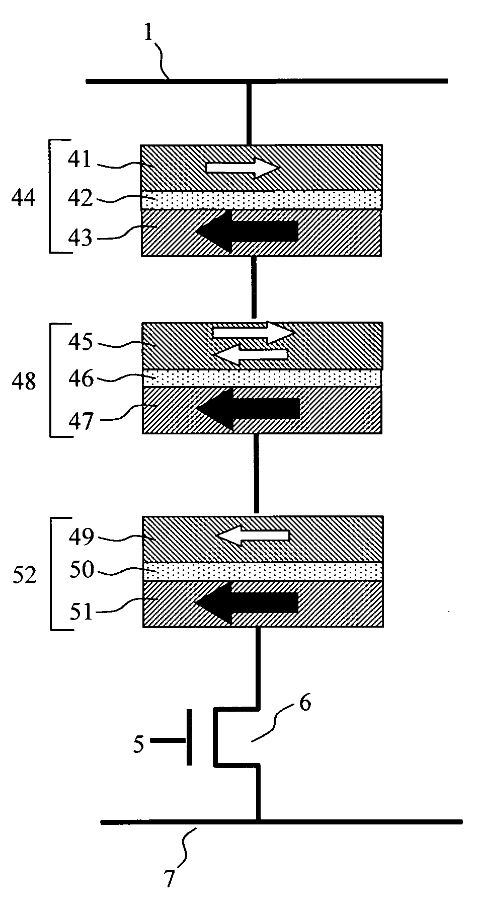
[0044]As already described, the TMR element shows a considerably higher resistance change rate than the GMR element, and therefore is suitable for a memory element. Moreover, when used as a spin torque oscillator, the TMR element can obtain considerably higher current amplitude Irf than when the GMR element is used, and therefore this example is one of the most realistic combinations.

[0045]The second TMR element used as a memory element has a film structure of Ta / NiFe / IrMn / CoFe / Ru / CoFeB / MgO / CoFeB / Ru / CoFeB / cap. IrMn is an antiferromagnetic film which fixes magnetization to one direction. CoFe / Ru / CoFeB is a synthetic ferri-fixed layer in which CoFe and CoFeB are exchange-coupled to each other through Ru. MgO is a barrier layer having a film thickness of about 0.9 nm. CoFeB / Ru / CoFeB is a synthetic ferri-free layer in which CoFeB and CoFeB are exchange-coupled to each other through Ru. Using the synthet...

example 2

Example in Which the Second Magnetoresistance Effect Element is a TMR Element and Other Magnetoresistance Effect Elements are GMR Elements

[0050]As already described, the TMR element shows a considerably higher resistance change rate than that of the GMR element, and therefore is suitable for a memory element. Moreover, the GMR element has resistance lower than that of the TMR element, and therefore is suitable for the use when the entire resistance is to be decreased.

[0051]The second TMR element used as a memory element has a film structure of Ta / NiFe / IrMn / CoFe / Ru / CoFeB / MgO / CoFeB / Ru / CoFeB / cap. IrMn is an antiferromagnetic film which fixes magnetization to one direction. CoFe / Ru / CoFeB is a laminated ferri-fixed layer in which CoFe and CoFeB are exchange-coupled to each other through Ru. MgO is a barrier layer having a film thickness of about 0.9 nm. CoFeB / Ru / CoFeB is a laminated ferri-free layer in which CoFeB and CoFeB are exchange-coupled to each other through Ru. Using the laminat...

example 3

Memory Cell Structure

[0055]A specific explanation will be next given of a memory cell structure of the present invention using FIGS. 10A and B. FIG. 10A is a cross-sectional view of the memory cell, and FIG. 10B is a plane view of the memory cell. First, a transistor is formed at a lowermost part of the memory. The transistor controls a current to be made to flow into the magnetoresistance effect elements. Reference numeral 105 is a separation section; 106 and 107 are a drain region and a source region, respectively, of the transistor. The source region 107 is connected to the source line 7 through a metal via 108. Reference numeral 104 is a word line for applying electric field to the transistor. On the other hand, the drain region 106 is connected to a metal 102 to be a base for manufacturing magnetoresistance effect elements through a metal via 103. Three magnetoresistance effect elements are formed on the metal 102 while interposing a metal intermediate film 101 between each set...


PUM


Abstract

Provided is a magnetic random access memory employing spin torque magnetization reversal having a small write current value is applied. The memory includes: a switching element the conduction of which is controlled by a gate electrode, and three magnetoresistance effect elements connected to the switching element in series. Each magnetoresistance effect element may be a TMR element or a GMR element that includes a multilayered film composed of a fixed layer, a non-magnetic layer and a free layer. The central element serves as a storage element. The magnetoresistance effect elements are manufactured such that an absolute value of current necessary for changing a magnetization direction of at least one of the magnetoresistance effect elements located at both ends is larger than an absolute value of current necessary for changing a magnetization direction of the central magnetoresistance effect element.

Description

CLAIM OF PRIORITY[0001]The present application claims priority from Japanese application JP 2007-333872 filed on Dec. 26, 2007, the content of which is hereby incorporated by reference into this application.BACKGROUND OF THE INVENTION[0002]1. Field of the Invention[0003]The present invention relates to a magnetic memory and a magnetic random access memory that employ spin torque magnetization reversal.[0004]2. Description of the Related Art[0005]In recent years, attention has been paid to a magnetic random access memory (MRAM) which can possibly replace the conventional dynamic random access memory (DRAM). As described in, for example, the specification of U.S. Pat. No. 5,734,605, the conventional MRAM employs the following recording system. Specifically, in a tunnel magnetoresistance effect element (TMR) having a multi-layer structure of magnetic film / non-magnetic insulating film / magnetic film, a magnetization of one of the magnetic films is reversed by using a synthetic magnetic f...

Claims


Application Information

Patent Timeline
IPC IPC(8): G11C11/14G11C11/00G11C11/416
CPCG11C11/16G11C11/1659G11C11/161G11C11/1675G11C11/15H10B61/22H10N50/10
Inventor ITO, KENCHI
Owner HITACHI LTD
Why Eureka
Try Eureka