Retardation film, method for producing retardation film, polarizing plate and liquid crystal display

a technology of retardation film and polarizing plate, which is applied in the direction of instruments, optical elements, transportation and packaging, etc., can solve the problems of remarkable lowering of contrast, dimensional stability, and film not always suitable, so as to improve light leakage and dimensional stability, and raise front-view contrast

Inactive Publication Date: 2009-07-02
KONICA MINOLTA OPTO
View PDF5 Cites 30 Cited by
  • Summary
  • Abstract
  • Description
  • Claims
  • Application Information

AI Technical Summary

Benefits of technology

[0017]An object of the invention is to provide a retardation film, a method of producing the retardation film and a liquid crystal display which are improved in the light leaking and the dimensional stability under high temperature and high humidity conditions and raised in the front-view contrast.

Problems solved by technology

Therefore, such the film is not always suitable for the purpose to improve the view angle of the VA type LCD, for example.
However, it is known that a large retardation film causes remarkable lowering in the contrast due to the discrepancy of slow axis in the in-plane direction.
However, it is the present situation that problems of contrast, dimensional stability under a high temperature and high humidity condition and light leaking as to the retardation film for large size display highly demanded recently, are required to be solved.

Method used


Image

  • Retardation film, method for producing retardation film, polarizing plate and liquid crystal display
  • Retardation film, method for producing retardation film, polarizing plate and liquid crystal display
  • Retardation film, method for producing retardation film, polarizing plate and liquid crystal display

Examples


example 1

Measurement of Glass Transition Temperature Tg of Film

[0294]Ten milligram of film sample was heated from −40° C. to 200° C. at a temperature raising rate of 20° C. / minute using a DSC instrument DSC220, manufactured by Seiko Instruments Inc., for obtaining an endothermic curve. Tangent lines were drawn after and before the inflection point of thus obtained endothermic curve and the crossing point of them is defined as the glass transition temperature Tg.

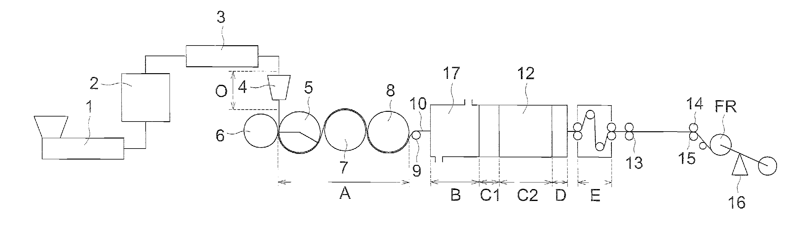
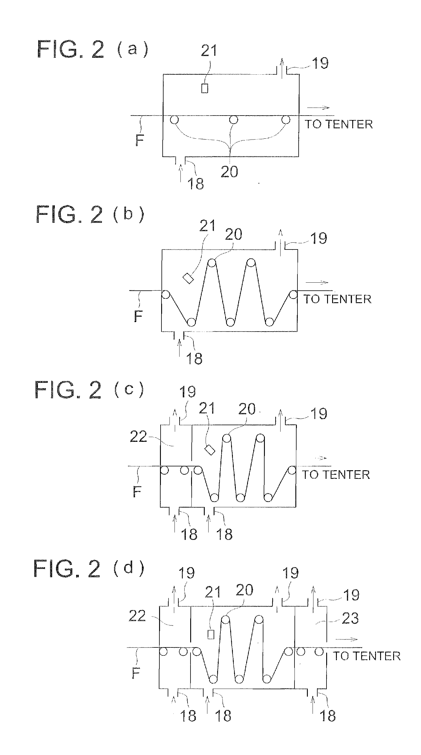
[0295]In the frying apparatus shown in FIG. 2, three non-contact type surface thermometers, Infrared Thermometer IT 2-80, manufactured by Keyence Corp., were arranged in the width direction of the film and the surface temperature of film was measured and the average of the measured values was defined as the temperature of the film.

>

(Preparation of Cellulose Ester Film)

(Materials to be Used)

[0296]C-1. Cellulose acetate propionate: Acetyl group

[0297]substitution degree=1.9, propionyl group substitution

[0298]degree=0.7, molecular weight ...

example 2

[0324]Retardation Films 17 to 27 were prepared in the same manner as in Example 1 except that the holding time in Step B was varied and the luminance was measured from the normal line direction in the same manner as in Example 1 for evaluating the front-view contrast.

[0325]The results of the evaluations are listed in Table 2.

TABLE 2Kind ofGlassHoldingRetar-thermo-transitionThermaltime indationplastictemperaturehysteresisFilm temperature (° C.)Step BRoRtRe-filmresin filmTg (° C.)patternStep AStep BStep C(sec.)(nm)(nm)Contrastmarks17*1143FIG. 3(a)90165140135145700Inv.18*1143FIG. 3(a)901651401035145750Inv.19*1143FIG. 3(a)901651402035145750Inv.20*1143FIG. 3(a)901651404035145750Inv.21*1143FIG. 3(a)901651405035145750Inv.22*1143FIG. 3(a)9016514010035145750Inv.23*1143FIG. 3(a)9016514030030160700Inv.24*1143FIG. 3(b)901651404030140680Inv.25*1143FIG. 3(b)901651403035145680Inv.26*1143FIG. 3(d)901301352035110520Comp.27*1143FIG. 3(d)901301354035115530Comp.*1: Cellulose ester type resin, Inv.: Inv...

example 3

[0327]Retardation film were prepared in the same manner as Examples 1 and 2 except that the tenter stretching apparatus was changed to that capable of independently varying the holding length (the distance from the beginning position to the end position of the holding) on right and left side, respectively, and the front-view contrast of the displays using thus obtained retardation films were determined by measuring the luminance from the normal line direction of the displaying face in the same manner as in Examples 1 and 2. It was understood that the retardation films of the invention improve the front-view contrast in the same or more degree compared with the retardation film of the invention obtained in Examples 1 and 2.


PUM

PropertyMeasurementUnit
thicknessaaaaaaaaaa
twist angleaaaaaaaaaa

Abstract

Disclosed are a retardation film, a method for producing the retardation film, a polarizing plate comprising the retardation film, and a liquid crystal display comprising the polarizing plate. Specifically disclosed is a method for producing a retardation film, which comprises an extrusion step for extruding a composition containing a thermoplastic resin and having a temperature of To [° C.] from a die; a cooling step for cooling a film extruded from the die and having a glass transition temperature of Tg [° C.] to a temperature Ta [° C.]; a heating step for heating the cooled film to a temperature Tb [° C.] at least once; and a stretching step for cooling the heated film to a temperature Tc [° C.] and then stretching the cooled film in the width direction.

Description

TECHNICAL FIELD[0001]The present invention relates to a retardation film, a method of producing retardation film, a polarizing plate and a liquid crystal display, in detail, to a retardation film improved in the light leaking and the dimensional stability under high temperature and high humidity conditions and effective for raising the front-view contrast of liquid crystal display, a method for producing the retardation film, a polarizing plate and a liquid crystal display.BACKGROUND ART[0002]Liquid crystal display is widely used as the displaying device of liquid crystal TV and personal computer since which can be driven at low voltage and low electric consumption and directly connected IC circuits and particularly the display can be made thinner. In the basic constitution of the liquid crystal display, polarizing plates are arranged on both sides of a liquid crystal cell, for example.[0003]There have been developed liquid crystal displays using twisted nematic liquid crystals (TN)...

Claims


Application Information

Patent Timeline
Patent Type & Authority Applications(United States)
IPC IPC(8): C09K19/02B29C47/88C08B1/00C08G63/00C08G64/00
CPCB29C55/08B29K2001/00B29K2001/12B29K2023/38B29K2067/00B29K2067/046Y10T428/10B29K2995/0034B29K2995/006G02B5/3083G02F1/1303G02F1/133634G02F2202/40B29K2069/00C09K2323/00C08J5/18G02F1/13363
Inventor YAMADA, RUMIKOSHIBUE, TOSHIAKIKUBO, NOBUO
Owner KONICA MINOLTA OPTO
Why Eureka
Try Eureka