Porous beta-sic-containing ceramic molded article comprising an aluminum oxide coating, and method for the production thereof

a technology of aluminum oxide coating and beta-sic, which is applied in the direction of exhaust treatment, filtration separation, lighting and heating apparatus, etc., can solve the problems of high wear and tear of extrusion nozzles, inability to produce stable molded bodies with passage structures, and poor adhesion ability of silicon carbide to catalysts, etc., to achieve high passage density

Active Publication Date: 2009-07-09
HELSA AUTOMOTIVE GMBH & CO KG
View PDF31 Cites 16 Cited by
  • Summary
  • Abstract
  • Description
  • Claims
  • Application Information

AI Technical Summary

Benefits of technology

[0007]A further object is to provide a process for the production of porous SiC-based ceramics which permi...

Problems solved by technology

Upon extrusion however the extrusion nozzles are subjected to a high level of wear.
In addition the production of stable molded bodies which have a passage structur...

Method used


Image

  • Porous beta-sic-containing ceramic molded article comprising an aluminum oxide coating, and method for the production thereof
  • Porous beta-sic-containing ceramic molded article comprising an aluminum oxide coating, and method for the production thereof
  • Porous beta-sic-containing ceramic molded article comprising an aluminum oxide coating, and method for the production thereof

Examples


example 1

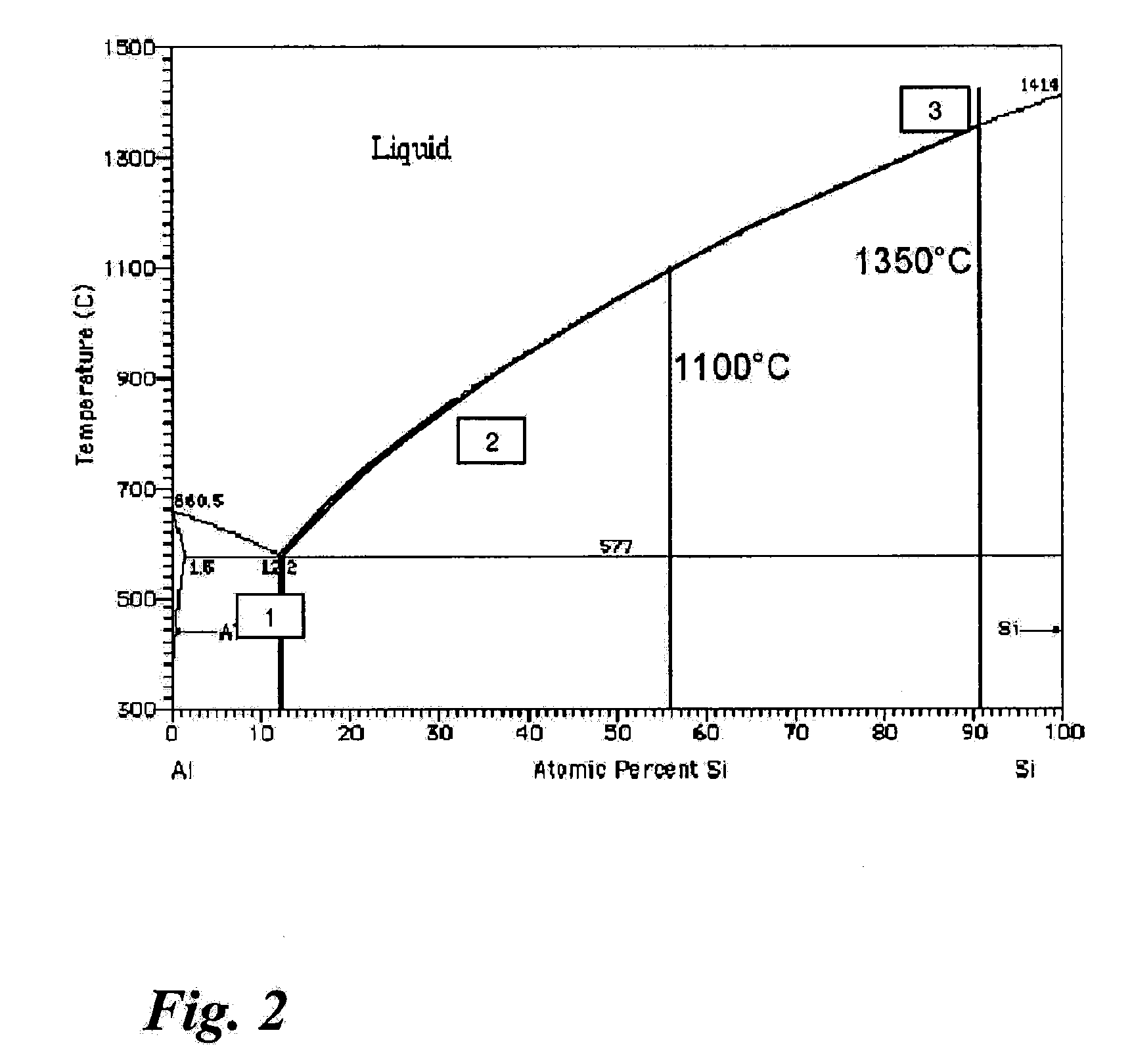
[0161]The melting point of aluminum is at about 660° C. The melting point of silicon is at about 1412° C. FIG. 2 shows for a composition with 90 atomic % Si and 10 atomic % Al alloy formation of aluminum and silicon at different temperatures during the pyrolysis and silicating operations.

[0162]During the first temperature procedure (pyrolysis) a eutectic melt involving the composition of 12.2 atomic % Si and 87.8 atomic % Al (point 1 in the diagram) is formed from 577° C. (eutectic point) at the Al-Si contact locations. If the temperature is further increased the melt is increasingly depleted in respect of Al as silicon additionally dissolves. At 850° C. (maximum temperature during pyrolysis in Example 1, point 2 in the diagram) there is theoretically a melt composition of about 33 atomic % Si and 67 atomic % Al. The proportion of Si in the melt however is much too low to permit SiC-formation. During the silicating operation the temperature is raised to a maximum of 1450° C. The pro...

example 2

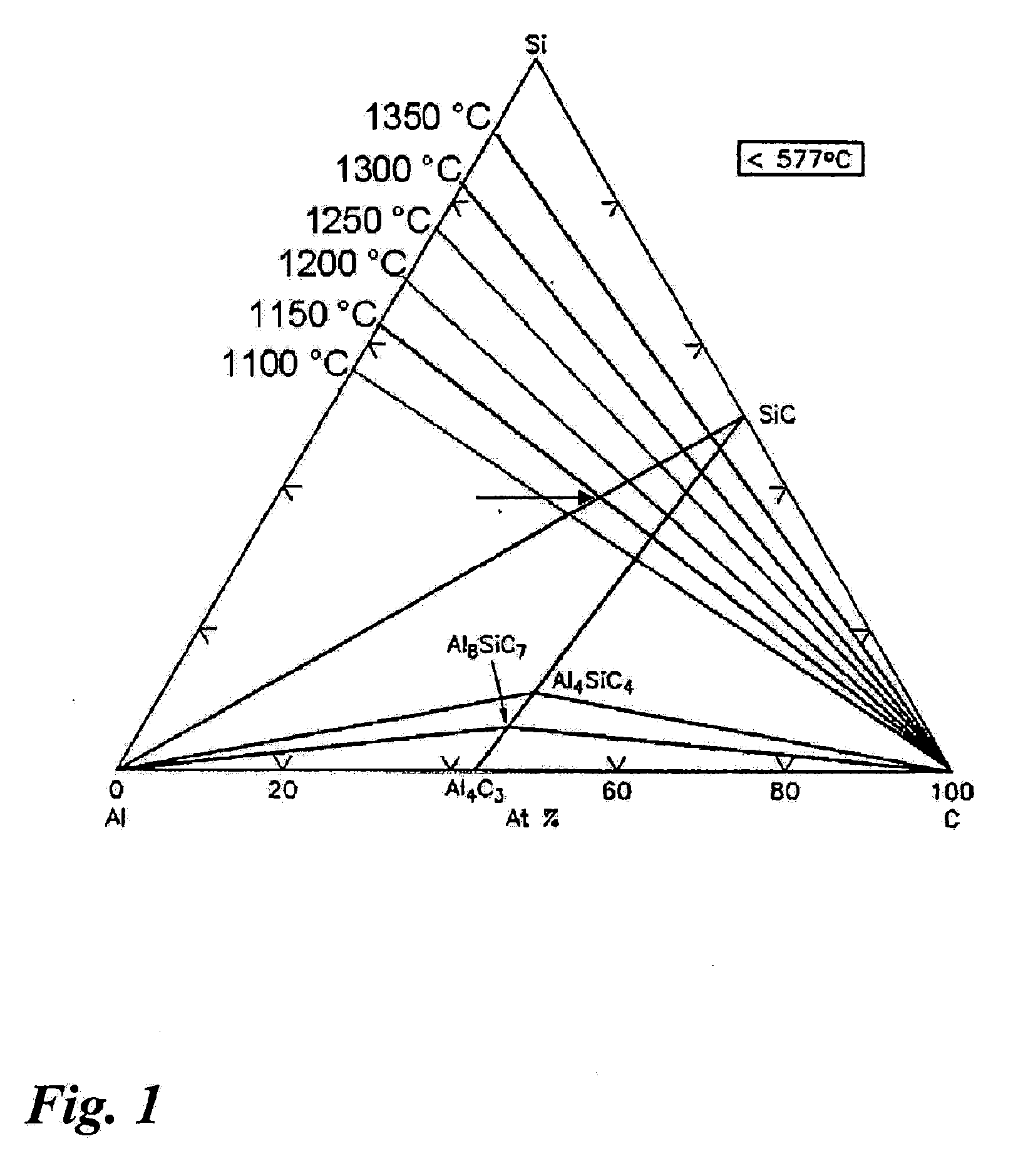
[0163]FIG. 1 and Table 1 show the ternary Al-Si—C-phase diagram and six possible alloy compositions. Table 1 gives the proportions in atomic %, Table 2 gives them in % by weight. If exactly those proportions are set, the respective melting points of the alloys and thus the corresponding silicating points are reached. The compositions of those alloys are within the Si—SiC—Al triangle, at the Al—SiC connecting line. In order to avoid the formation of the carbide Al4SiC4 that connecting line should not be exceeded in the direction of the SiC—Al4SiC4—Al triangle. If such a carbide were to be formed the mechanical strength of the filter fails greatly and distribution of the aluminum layer becomes less uniform. For that reason the selected proportions in Tables 1 and 2 are also just above that Al—SiC line.

TABLE 1Composition of the possible AlSiC-alloys in atomic %AlSiC1100° C.28.136.535.41150° C.22.938.538.31200° C.18.541.040.51250° C.14.043.242.81300° C.10.345.144.61350° C.5.247.647.2

TAB...

example 3

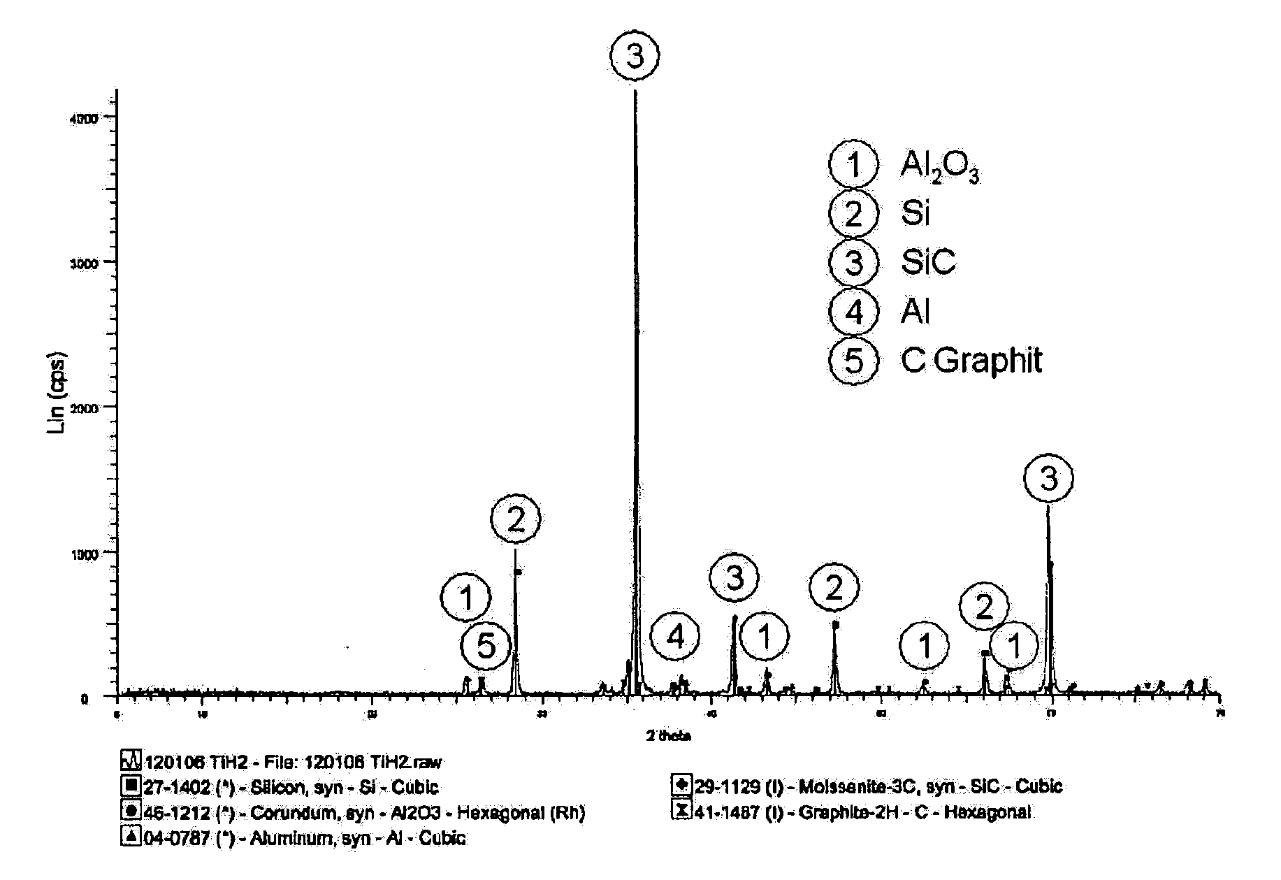
[0164]Taking the starting material, a honeycomb body with 200 cpsi was produced by extrusion, dried and pyrolyzed at 850° C. The pyrolyzed body was then heated In an argon atmosphere to 1250° C. or 1350° C. and kept at that temperature for 1 hour.


PUM

PropertyMeasurementUnit
Temperatureaaaaaaaaaa

Abstract

The invention concerns a process for the production of a porous β-SiC-bearing ceramic molded body that includes an aluminum oxide layer at the surface of the pores and passages of the porous β-SiC-bearing ceramic molded body. The invention further concerns a porous β-SiC-bearing ceramic molded body which has pores of a mean pore size in the range of between 0.1 urn and 50 μm and an aluminum oxide layer at the surface of the open pores and passages.

Description

CROSS-REFERENCE TO RELATED APPLICATIONS[0001]This application is a national stage filing of PCT / EP2006 / 006559 filed Jul. 7, 2006 claiming priority to EP 05014530.9 filed Jul. 5, 2005 and EP 05014531.7 filed Jul. 5, 2005.TECHNICAL FIELD[0002]The invention concerns a porous β-SiC-bearing ceramic molded body with an aluminum oxide layer at the surface and a process for the production thereof.BACKGROUND OF THE INVENTION[0003]SiC-based materials are employed for a large number of different uses, in particular where high stability at high temperatures or high levels of resistance to corrosion are required. Highly porous and thus also lightweight, SiC-based ceramics are increasingly required as catalyst carriers, combustion aids, Insulating materials, substrate materials or for gas heating in pore burners or for solar installations and for exhaust gas cleaning at high temperatures as filter materials.[0004]SiC-materials on an SiC-base are produced either on the basis of SiC-powders (U.S. P...

Claims


Application Information

Patent Timeline
IPC IPC(8): B32B5/18B28B3/20B01J32/00B01D46/00
CPCB01D46/0001Y10T428/268B01D46/2444B01D46/2466B01D46/247B01D46/2474B01D2046/2437B01D2046/2481B01D2046/2485B01J27/224B01J35/04B01J37/0018B01J37/0215C04B35/565C04B35/573C04B35/6263C04B35/62655C04B35/6267C04B38/0022C04B41/009C04B41/5031C04B41/87C04B2111/00129C04B2111/0081C04B2235/3217C04B2235/402C04B2235/404C04B2235/422C04B2235/428C04B2235/48C04B2235/5292C04B2235/5296C04B2235/5409C04B2235/5436C04B2235/6021C04B2235/762C04B2235/80F01N3/0222F01N3/2828F01N2370/02B01D46/2418Y02T10/20C04B38/0006C04B38/0054C04B38/0074C04B41/0072C04B41/4556Y02T10/12B01D46/24492B01D46/2484B01D46/2482B01D46/2429
Inventor TRAVITZKY, NAHUMGALSTERER, DANIELGREIL, PETERWOLFF, THOMASSIEBER, HEINOWEISENSEL, LARS
Owner HELSA AUTOMOTIVE GMBH & CO KG
Why Eureka
Try Eureka