Method for combusting fuel

a fuel combustion and fuel technology, applied in the field of combusting fuel, can solve the problems of reducing the propagation speed of the flame, reducing the combustion efficiency, and presenting high nitrogen oxide emissions caused by the combustion of the lean envelope, so as to achieve a lower fuel consumption and reduce raw emissions , the effect of high efficiency

Inactive Publication Date: 2009-07-16
ROBERT BOSCH GMBH
View PDF34 Cites 1 Cited by
  • Summary
  • Abstract
  • Description
  • Claims
  • Application Information

AI Technical Summary

Benefits of technology

[0003]The method according to the present invention for combusting fuel in a combustion chamber of an internal combustion engine has the advantage that by igniting the at least one layer charge cloud at different locations within the combustion chamber, the mixture cloud combusts more rapidly at the same combustion rate at a higher maximum pressure. This enables combustion with higher efficiency whereby the fuel consumption may be lowered. The raw emissions may be lowered by the ignition taking place at instants at which the mixture homogeneity is established and the mean air / fuel ratio changes only a little due to faster combustion and a better burnout takes place.
[0004]Ignition at the ignition points may be carried out simultaneously or also staggered in time. In the former case, a rapid fuel conversion is achieved at a high pressure rise, thereby increasing the combustion efficiency. In the latter case, a retardation of the combustion takes place in contrast to the former case, having the advantage of noise reduction and lower component stress. Overall, the desired pressure curve may be formed by multiple ignitions at different points in time, whereby a burnout may be achieved as rapidly as possible at as many as possible ignition points. By shaping the pressure curve, the chronological sequence of fuel conversion and noise may be controlled. The ignition points may be situated symmetrically or asymmetrically in the combustion chamber. Knocking may be avoided if the ignition points are situated in regions that are prone to knocking, e.g., close to the hot exhaust valves.

Problems solved by technology

The high nitrogen oxide emissions caused by the combustion of the lean envelope present challenges.
However, by increasing the exhaust gas recirculation rate, the propagation speed of the flame is reduced, which in turn lowers the combustion efficiency.

Method used


Image

  • Method for combusting fuel
  • Method for combusting fuel

Examples


Embodiment Construction

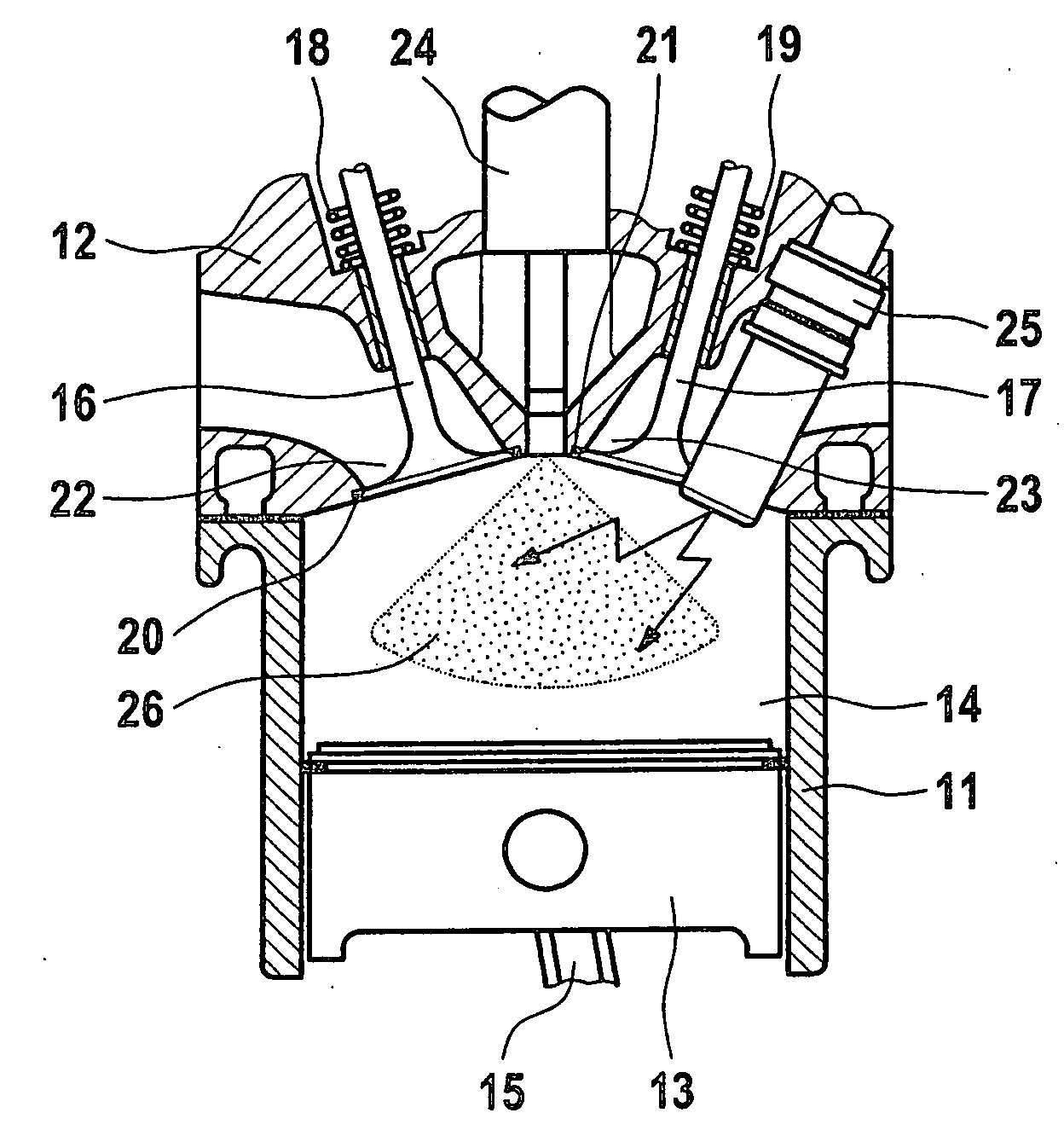
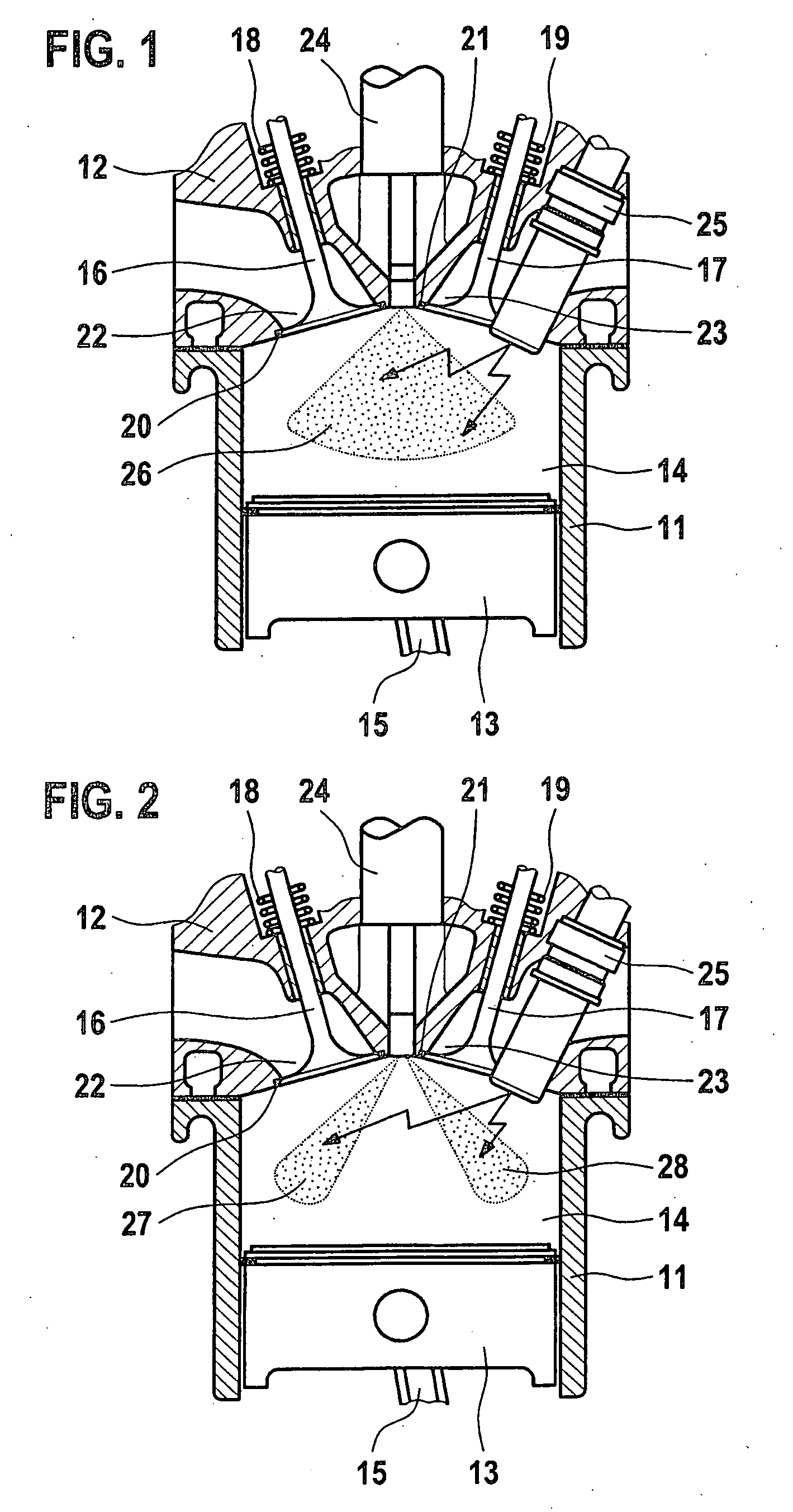
[0007]The combustion cylinder shown in detail in a longitudinal section in FIGS. 1 and 2 has a cylinder cavity 11 and a cylinder head 12 covering cylinder cavity 11. A piston 13, which, together with cylinder head 12 in cylinder cavity 11 encloses a combustion chamber 14, is axially movably guided in cylinder cavity 11. Piston 13 is connected to a crankshaft (not shown) of an internal combustion engine in a known manner via a connecting rod 15. An intake valve 16 and an exhaust valve 17 are situated in cylinder head 12 and rest under the effect of valve closing springs 18 and 19, with a valve disk, on a valve seat 20, 21 formed in cylinder head 12 and which are lifted from valve seats 20 and 21 with the aid of a valve operating mechanism (not shown here). Valve seat 20 encloses a combustion chamber inlet 22 for supplying combustion air, and valve seat 21 encloses a combustion chamber outlet 23 for discharging the combusted exhaust gases.

[0008]Furthermore, a fuel injector 24 for inje...


PUM


Abstract

A method for combusting fuel in a combustion chamber of an internal combustion engine, in which air is supplied to the combustion chamber via at least one intake valve and at least one fanned-out fuel spray is injected into the combustion chamber via at least one fuel injector in such a way that at least one layer charge cloud composed of a fuel/air mixture is produced and the layer charge cloud is ignited using at least one ignition device. For achieving a higher degree of efficiency during combustion, the at least one layer charge cloud is ignited in the combustion chamber at at least two spatially separated ignition points, the ignition being carried out simultaneously or staggered in time.

Description

FIELD OF THE INVENTION[0001]The present invention is directed to a method for combusting fuel in a combustion chamber of an internal combustion engine.BACKGROUND INFORMATION[0002]A known fuel injection system (German Patent Application No. DE 100 32 336) has a fuel injector, which injects fuel directly into a combustion chamber delimited by a cylinder wall and a piston guided therein, and a spark plug protruding into the combustion chamber. The fuel injector produces a cone-shaped injection spray in the combustion chamber through at least one row of injection orifices which are situated around the circumference of a valve body. A centrally located injection orifice is additionally provided in the valve body which produces a fuel-enriched central area of the injection spray which reaches the spark plug. This forms a mixture cloud in the combustion chamber which has a stoichiometric or slightly rich core (0.8<λ<1.1) and a lean envelope (1.5<λ). If the core of the mixture clou...

Claims


Application Information

Patent Timeline
Patent Type & Authority Applications(United States)
IPC IPC(8): F02B5/00
CPCF02B5/02F02B17/005Y02T10/123F02B2075/125Y02T10/12F02B23/101
Inventor ROGLER, PHILIPP
Owner ROBERT BOSCH GMBH
Why Eureka
Try Eureka