Method of fabricating solder bumps

Active Publication Date: 2009-07-16
IBM CORP
View PDF6 Cites 21 Cited by
  • Summary
  • Abstract
  • Description
  • Claims
  • Application Information

AI Technical Summary

Benefits of technology

[0017]FIGS. 2(A) through (G) are schematic diagrams depicting a cross sectional views of another embodiment of the inventive structure fabricated via the two step IMS of the inventive process wit

Problems solved by technology

However, the high tin (Sn) content of these common eutectic Pb-free solder bumps are typically unreliable and subject to failure due to the rapid consumption of UBM (Under Bump Metallurgy) during several reflow process and during the operation at high temperature under high current.
However, its high cost is prohibitive for high volume commercial product applications.
Further, a second problem with an AuSn solder is that the exact eutectic composition needs to be maintained throughout the process to avoid the abrupt increase of the melting temperature of Au—Sn solder.
The low stand-off height is a concern from the fatigue life point of view due to higher shear strain after assembly.
Also, the low stand-off height between the chip and the substrate and the small gap among the joints makes it difficult to clean the flux residue and underfill the module.
Also, the electroplating method of the first solder can not handle wide alloy range.
This method is very expensive in that a thick photoresist process is needed to fabricate two step of e

Method used


Image

  • Method of fabricating solder bumps
  • Method of fabricating solder bumps
  • Method of fabricating solder bumps

Examples


Example

EXAMPLE 1

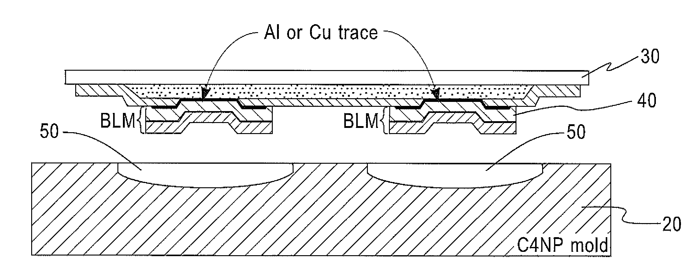
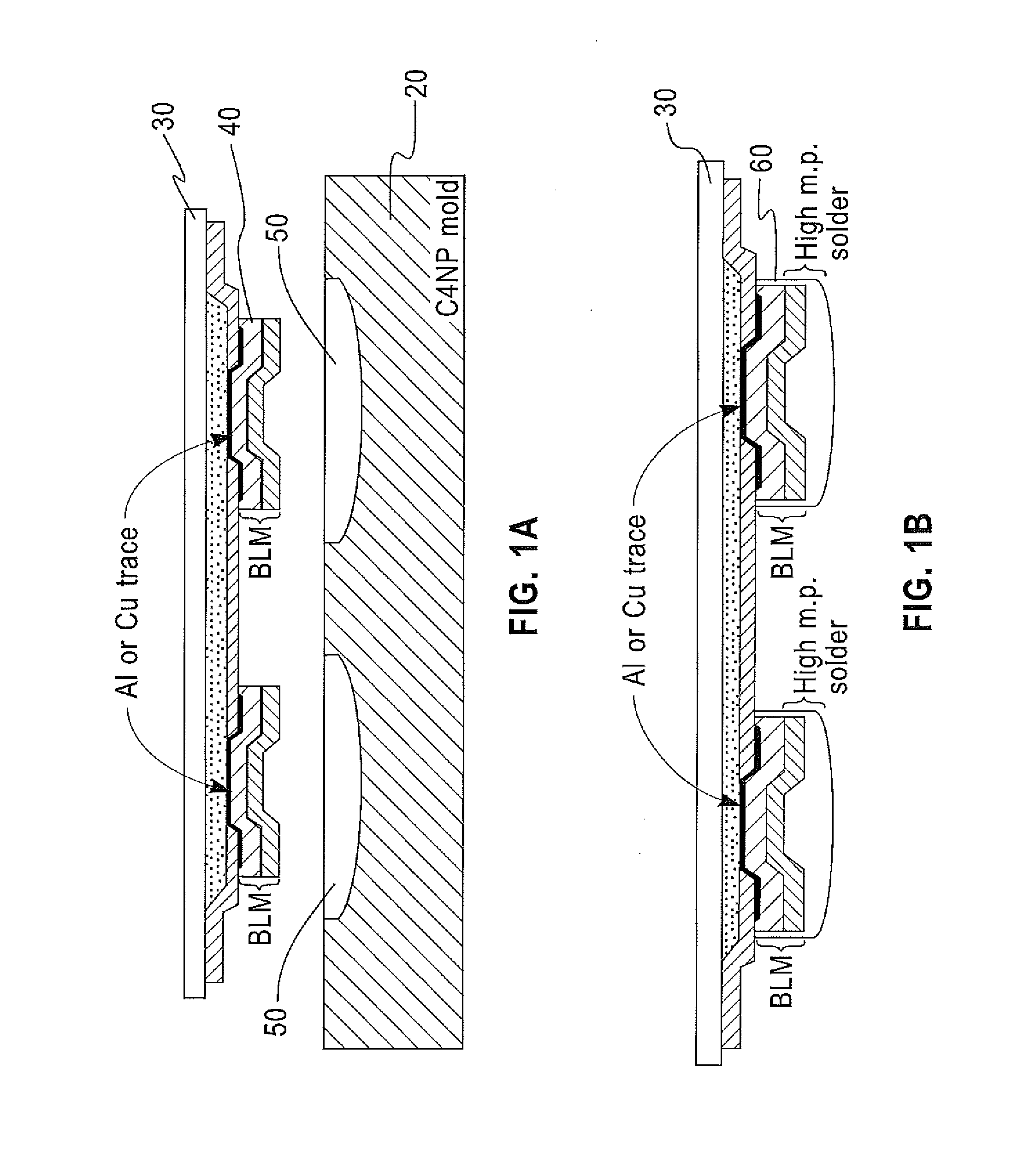
[0039]A mold was filled with a high melting temperature material (about 280° C., Au-20 wt % Sn) relative to the proposed second solder material, and a solder is transferred onto a UBM on a Si wafer. A C4NP mold was then filled with a low melting temperature material (about 221° C., Sn-3.5 wt % Ag) relative to the first solder material, and a solder transferred onto the first solder on the UBM on the Si wafer.

[0040]The resulting solder was used for the flip chip assembly of a chip to a substrate by melting of only a low melting temperature material.

Example

EXAMPLE 2

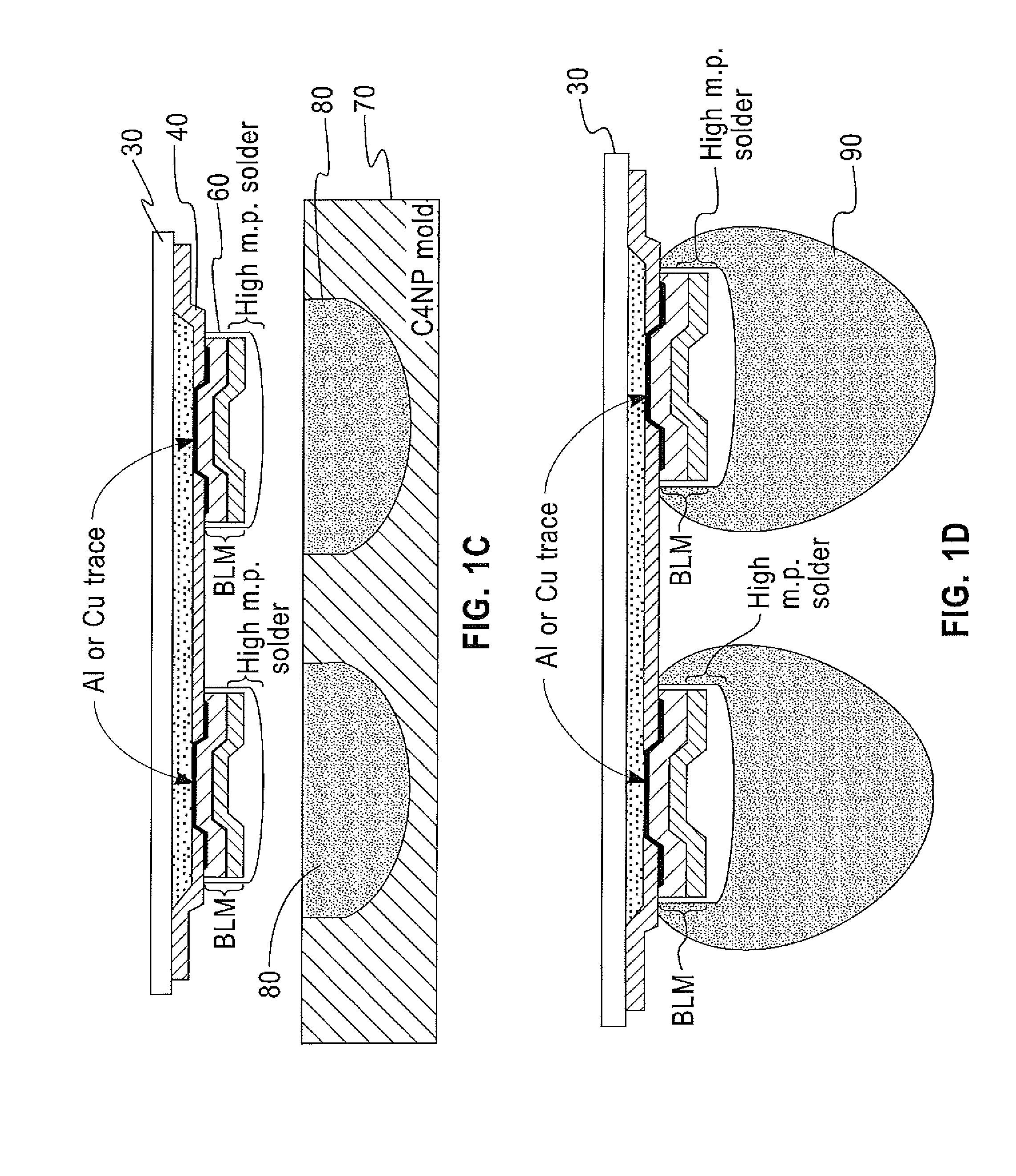
[0041]A mold was filled with a low melting temperature material (about 221° C., Sn-3.5 wt % Ag) relative to the proposed second solder material, and a solder is transferred onto a UBM on a Si wafer. A transfer substrate (mold) having cavities with a high aspect ratio corresponding to positions of associated solder structures was then filled with a high melting temperature material (about 280° C., Au-20 wt % Sn) relative to the first solder material, and a columnar solder was transferred onto the first solder on the UBM on the Si wafer.

[0042]The resulting solder was used for the flip chip assembly where the joints has a high aspect ratio. The columnar high melting temperature material does not melt during the assembly process on the substrate because on the low melting temperature solders on the substrate melts and makes joints as shown in FIG. 2(G).

[0043]The invention has been described in terms of preferred embodiments thereof, but is more broadly applicable as will be und...


PUM

PropertyMeasurementUnit
Temperatureaaaaaaaaaa
Percent by massaaaaaaaaaa

Abstract

A semiconductor solder bump structure having a solder bump with at least a first solder and a second solder attached to the first solder, producing one solder bump having at least two different solders with different melting temperatures. A method of fabricating the solder is included.

Description

FIELD OF INVENTION [0001]The present invention relates to semiconductor packaging technology, particularly, a two-step solder with different melting temperatures within one solder bump.BACKGROUND OF THE INVENTION [0002]Lead (Pb)-containing solders have been used in microelectronic applications to form electrical interconnections between packaging levels, to facilitate heat dissipation from active devices, to provide mechanical / physical support, and to serve as a solderable surface finish layer on printed circuit boards (PCBs) and lead frames. For example, Pb-containing solders are employed in C4 (controlled collapse chip connection) solder joints, or bumps, connecting a silicon chip to a BT-resin-based laminate chip carrier and BGA solder joints, or balls, connecting the module to a PCB. The C4, or flip-chip, solder joints are generally used to attach flip-chips to ceramic multichip modules (MCMs) for mainframe computers or high-end servers. The flip-chip has become pervasive becaus...

Claims


Application Information

Patent Timeline
IPC IPC(8): B23K31/02B32B3/10
CPCB23K1/0016B23K1/19B23K35/262Y10T428/24942B23K2201/36H01L24/11Y10T428/24826B23K35/3013H01L2924/01322H01L2224/1111H01L2224/11003H01L2224/05027H01L2224/0508H01L2224/05001H01L2224/05572H01L2224/05124H01L2224/05147H01L2224/056B23K2101/36H01L24/06H01L24/05H01L24/13H01L2924/00H01L2924/00014
Inventor BUCHWALTER, STEPHEN L.GRUBER, PETER A.NAH, JAE-WOONGSHIH, DA-YUAN
Owner IBM CORP
Why Eureka
Try Eureka