Mineral extraction system and process

a technology of mineral extraction and extraction system, applied in the field of minerals extraction, can solve the problems of inefficient use of liquid solvent, unprocessed ore, high operating cost, and low yield, and achieve the effect of low capital cost and cost effectiv

Inactive Publication Date: 2009-07-23
DEVERE MINING TECH
View PDF3 Cites 5 Cited by
  • Summary
  • Abstract
  • Description
  • Claims
  • Application Information

AI Technical Summary

Benefits of technology

[0034]The Trench Leaching System has the advantage that it processes ore on a large scale, with low capital cost, using minimal handling of the ore and is considerably more cost effective than conventional mineral extraction processes. Thus, the Trench Leaching System has most of the advantages of heap leaching, tank leaching and vat leaching, but without many of their inherent disadvantages.
[0035]The operation of the Trench Leaching System relies upon the random movement of the liquid solvent in relatively narrow channels upwards through a charge of ore placed in a trench. These channels are somewhat similar to those of heap leaching—except that in heap leaching the liquid solvent tends to flow downwardly in “rivers” that are fixed in their route through the ore. In the Trench Leaching System, the ore within the random channels of upwardly flowing liquid solvent is subject to agitation, which liberates the valuable mineral in a manner similar to that of tank leaching, without the mechanical stirrers and associated energy requirements. This random channelling of the liquid solvent produces a migration of the liquid solvent through substantially the entire charge of ore, resulting in agitation of substantially all of the ore particles, thus giving a yield similar to that of tank leaching. The remainder of the charge of ore is static and in contact with the liquid solvent in much the same manner as vat leaching, which has the advantage of starting to dissolve the valuable mineral in preparation for agitation by the random channelling, which is not achieved by vat leaching.

Problems solved by technology

The problems of heap leaching include:Varying concentrations of mineral ore resulting in over and under utilisation of liquid solvent, resulting in inefficient use of liquid solvent, unprocessed ore and excessive operating costs.Restricted flow of liquid solvent due to compaction and silting up.The retention of the mineral-containing chemical in the crushed ore body, resulting in lower yields.Chemical spillage, leakage, dust creation, and dilution by rainwater.The tendency of liquid solvent to flow in fixed channels (referred to as “rivering”), thus bypassing the unprocessed ore.Solar loading, which can greatly increase the operating temperature of the excavated heap, seriously reducing the effectiveness of the leaching operation.
A serious problem associated with some heap leach installations is that they can fail to release any of their valuable minerals.
According to the leading operators of heap leach installations, there is no way to overcome such failed heap leaches.
In particular, to date there has been no reprocessing that can economically yield profits from a failed heap leach.
The main problem of tank leaching is the high cost of construction and operation of the process, with significantly higher costs per tonne when compared to heap leaching.
The high cost and compact nature of the tank leaching system minimises the ability to economically process large quantities of low-grade ore.
The main limitation of vat leaching is that particle sizes must be maintained relatively large, i.e. −6 mm, so that the liquid solvent can drain downwardly through the body of ore.
There are a large number of mineral bearing ore bodies that cannot be economically processed by any of these three prior art leaching techniques.

Method used


Image

  • Mineral extraction system and process
  • Mineral extraction system and process
  • Mineral extraction system and process

Examples


Embodiment Construction

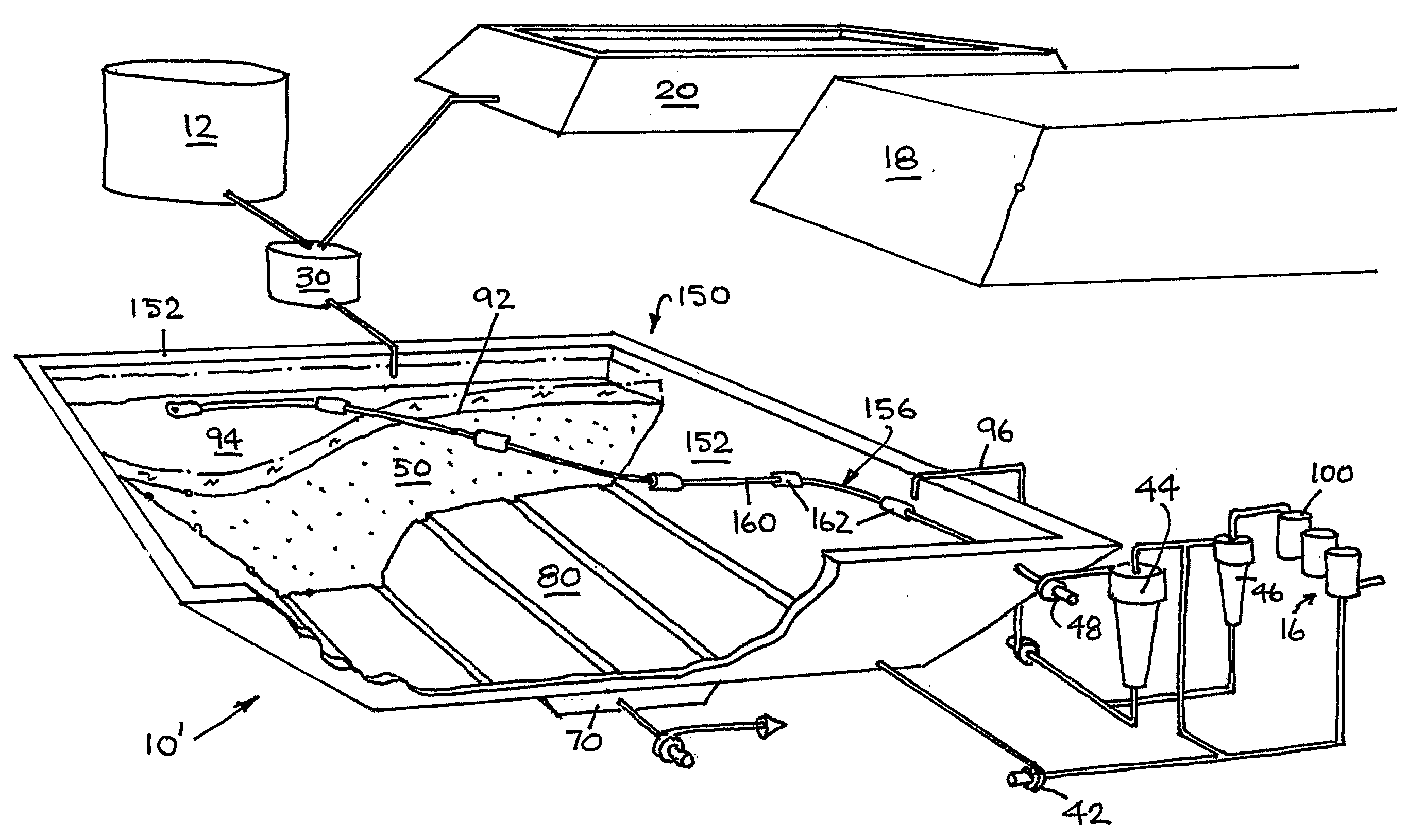
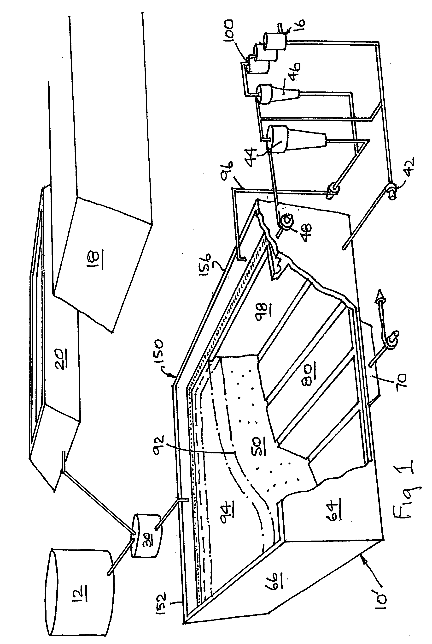
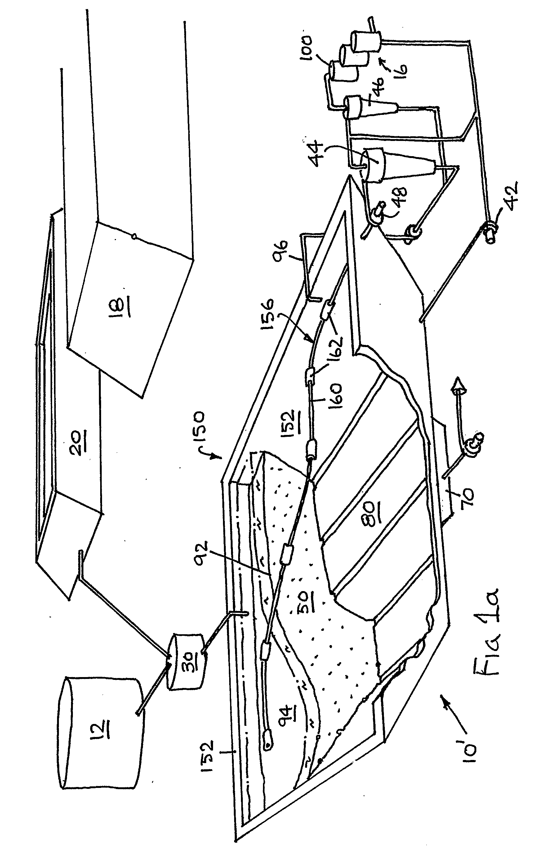
[0045]In FIGS. 1 and 2 there is shown an exemplary embodiment of the Trench Leaching System 10 in accordance with the present invention. The Trench Leaching System 10 includes a crushing circuit 12, a leaching circuit 14, a stripping circuit 16, a waste circuit 18 and a water reservoir 20.

[0046]The crushing circuit 12 is typically of conventional form and is designed to provide ore outputs with particle sizes of 12 has a pulp density control system 30 for delivering the crushed ore in a slurry form to the leaching circuit 14.

[0047]It is also envisaged that in reprocessing of tailings dumps, no crushing circuit will be required.

[0048]It is also envisaged that the ore could be introduced to the leaching circuit in a dry form.

[0049]The leaching circuit 14 includes a processing tank 40, a sparging pump 42, a main wet cyclone 44, a secondary bleeder cyclone 46 and a slurry pump 48.

[0050]The output of the pulp density control system 30 is plumbed into the upper reaches of the processing t...


PUM

PropertyMeasurementUnit
angleaaaaaaaaaa
timeaaaaaaaaaa
particle sizeaaaaaaaaaa

Abstract

A trench leaching system including a tank containing a charge of ore flooded with a liquid solvent up to the level of a gutter. A pump recirculates the solvent upwardly through the charge of ore via a sparging array for dissolving minerals which are reclaimed through a series of cyclones and stripped out of the pregnant solvent by a carbon column. The rate and pressure of the solvent flowing through the sparging array upwardly though the of ore are kept below the amount that would fluidise the ore and at an amount that produces channels which follow random paths that vary with time through the ore, wherein particles of ore in the channels are agitated by the solvent and wherein particles of ore outside the channels are maintained substantially static and in contact with the liquid solvent. Such a system can process low grade ore at low operating and capital costs.

Description

FIELD OF THE INVENTION[0001]The present invention relates to the extraction of minerals from a charge of ore using a lined trough in which a mineral extraction process is undertaken.[0002]More particularly, the present invention relates to a system and process for the extraction of minerals from a charge of ore placed in a trough, using leaching techniques, substantially at atmospheric pressure and temperature.BACKGROUND TO THE INVENTION[0003]A number of valuable metals (e.g. gold, copper, nickel, tungsten) are held in very small quantities (e.g. typically from 1 to 100 ppm) in large ore bodies. To extract these minerals, the ore must be crushed and sometimes ground, to allow a liquid chemical solvent (e.g. sulphuric acid, hydrochloric acid, sodium cyanide) to dissolve the valuable minerals, or to allow bacteria to access the valuable minerals. The dissolved minerals drain out from the ore carrying the valuable minerals. The solution can be further processed to remove the valuable m...

Claims


Application Information

Patent Timeline
Patent Type & Authority Applications(United States)
IPC IPC(8): B22F9/20B03B5/00
CPCC22B3/02C22B11/08C22B11/04Y02P10/20
Inventor MAWBY, AARON BRUCEGIRAUDO, CLINTON JOHNDEVERE, NICHOLAS GEOFFREY
Owner DEVERE MINING TECH
Why Eureka
Try Eureka