Optical head device and optical information reproducing device

a head device and optical information technology, applied in the direction of data recording, disposition/mounting of heads, instruments, etc., can solve the problems of deterioration of recording/reproducing characteristics, avoid adverse effects of recording/reproducing characteristics, and improve the signal to noise ratio of rf signals.

Inactive Publication Date: 2009-07-30
NEC CORP
View PDF3 Cites 0 Cited by
  • Summary
  • Abstract
  • Description
  • Claims
  • Application Information

AI Technical Summary

Benefits of technology

[0013]An object of the present invention is to provide a method for detecting radial tilt of an optical recording medium in an optical head device, optical head device and an optical information recording / reproducing device, which can obtain excellent signal to noise ratio of the RF signal, through overcoming the above-described problems in a conventional optical head device which is capable of detecting radial tilt of a read-only type optical recording medium.
[0018]The optical information recording / reproducing device of the present invention comprises the optical head device of the present invention as described and a correcting means for correcting radial tilt of the optical recording medium. In the optical information recording / reproducing device of the present invention, the radial tilt of the optical recording medium is corrected so as to prevent adverse effect on the recording / reproducing characteristics using the optical head device of the present invention as described.
[0019]When detecting the radial tilt of the optical recording medium in the optical head device and the optical information recording / reproducing device of the present invention, the main beam used for detecting the RF signal from the optical recording medium can be received by the four light receiving sections. Therefore, the number of current-voltage conversion circuits for the main beam is the same as that in an ordinary optical head device which does not detect radial tilt. As a result, there is no increased noise due to the circuit thereby achieving excellent signal to noise ratio of the RF signal.
[0020]Next, it will be described in short by referring to FIG. 1. Light emitted from a semiconductor laser 1 is divided into three light beams, which are 0th-order light as the main beam and ±1st-order diffracted lights as the sub-beams, and track error signals from each of the main beam and the sub-beams are obtained by a differential phase detection method. By the effect of a diffractive optical element 3a, the intensity distributions of the main beam and the sub-beams differ when making incidence on an objective lens 6. Therefore, when there is radial tilt in a disk 7, the phases of the track error signals by the main beam and the sub-beams are shifted with each other. Based on the phase shift of the track error signals, the radial tilt of the disk 7 is detected. Thereby, it becomes possible to achieve an excellent signal to noise ratio of the RF signal when detecting the radial tilt of read-only type optical recording medium.

Problems solved by technology

On the other hand, when the optical recording medium tilts against the objective lens in the radial direction, the shape of the focused spot becomes disturbed due to coma aberration caused by a substrate of the optical recording medium so that the recording / reproducing characteristics become deteriorated.

Method used


Image

  • Optical head device and optical information reproducing device
  • Optical head device and optical information reproducing device
  • Optical head device and optical information reproducing device

Examples


first embodiment

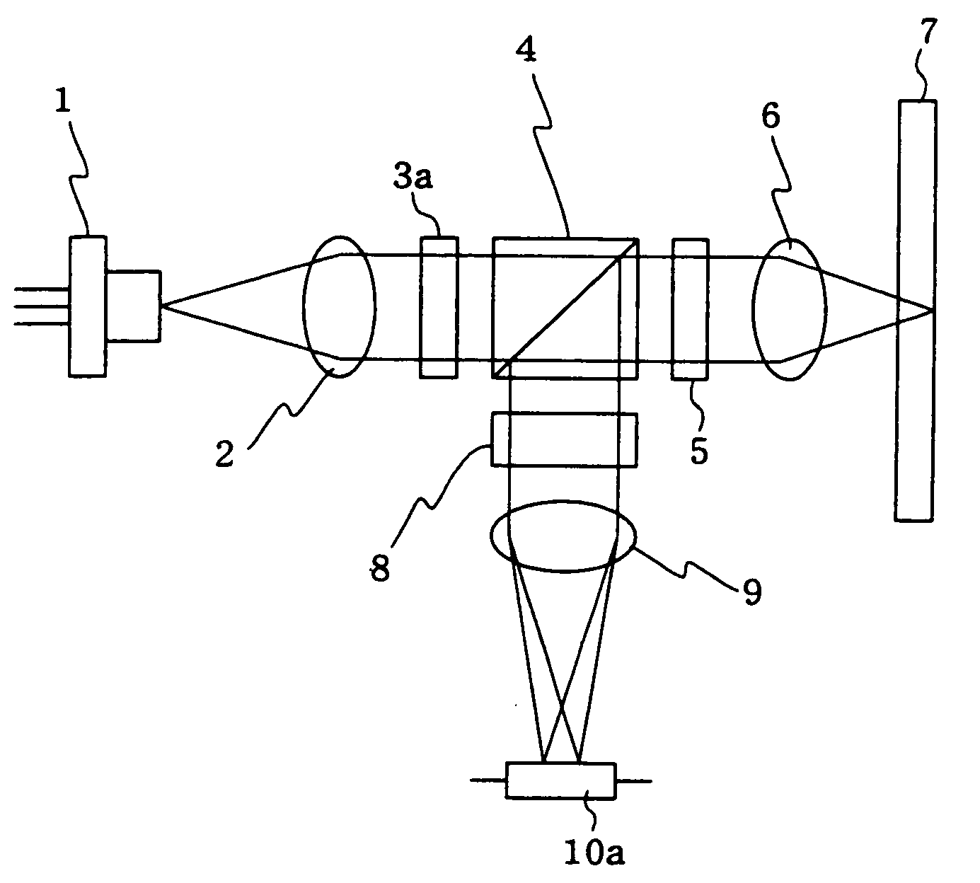
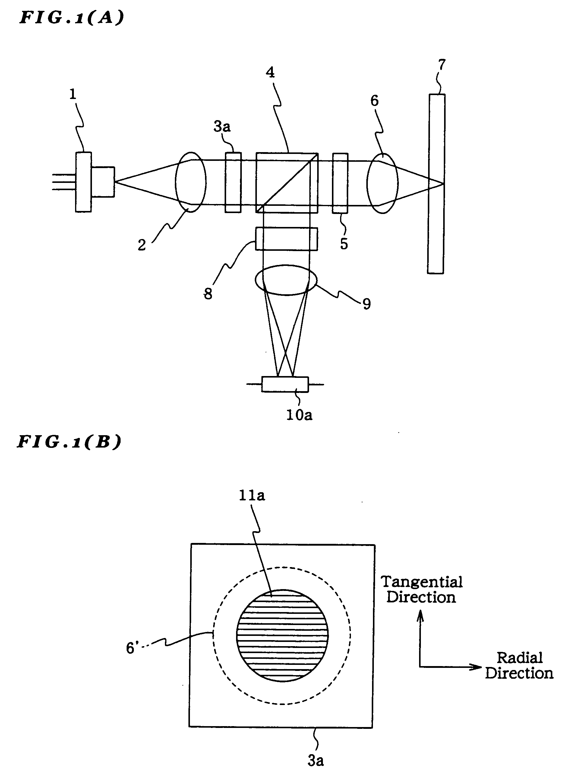
[0031]FIG. 1(A) shows an optical head device according to the present invention. Light emitted from a semiconductor laser 1 is collimated by a collimator lens 2. The collimated light is then divided into three light beams by a diffractive optical element 3a which are 0th-order light as a main beam and ±1st-order diffracted lights as sub-beams. The light beams enter a polarizing beam splitter 4 as P polarized light and substantially 100% transmit therethrough. Then, they transmit through quarter-wave plate 5 to be converted from linearly polarized light to circularly polarized light thereby to be focused onto a disk 7 by an objective lens 6.

[0032]Three light beams reflected from the disk 7 transmit inversely through the objective lens 6 and then transmit the quarter-wave plate 5 to be converted from the circularly polarized light to linearly polarized light whose polarization direction is orthogonal to that in the outward path. The light beams then enter the polarizing beam splitter ...

fourth embodiment

[0062]In the first to fourth embodiment, when there is residual error, caused by eccentricity of the disk 7 and the like, in the track error signal used for applying track servo, offset due to the residual error is also generated in the track error signal by the sub-beams as the radial tilt signal.

[0063]However, if the signal obtained by subtracting the track error signal used for applying the track servo from the track error signal by the sub-beams is used as the radial tilt signal, it is possible to detect radial tilt without generating offset in the radial tilt signal due to the residual error.

[0064]In a fifth embodiment of an optical head device according to the present invention, the diffractive optical element 3a in the first embodiment is replaced with a diffractive optical element 3e. FIG. 5(A) is a plan view showing the diffractive optical element 3e. The diffractive optical element 3e has the following structure. Diffraction gratings, which are divided into two regions 11e...


PUM

PropertyMeasurementUnit
differential phase detection methodaaaaaaaaaa
light intensity distributionsaaaaaaaaaa
diameteraaaaaaaaaa

Abstract

The light emitted from a semiconductor laser is divided by a diffractive optical element into three light beams which are 0th-order light as the main beam and ±1st-order diffracted lights as the sub-beams, and the track error signals by the main beam and the sub-beams are detected, respectively, by a differential phase detection method. By the effect of the diffractive optical element, the light intensity distributions of the main beam and the sub-beams become different when making incidence on an objective lens. Therefore, when there is radial tilt in a disk, the phases of the track error signals by the main beam and the sub-beams are shifted with each other. Based on the shift in the phases of the track error signals, radial tilt of the disk is detected.

Description

CROSS-REFERENCE TO RELATED PATENT APPLICATIONS[0001]This application is a division of application Ser. No. 10 / 437,915, filed May 15, 2003, now pending, and based on Japanese Patent Application No. 2002-149074, filed May 23, 2002, by Ryuichi Katayama, which are incorporated herein by reference in their entirety. This application claims only subject matter disclosed in the parent application and therefore presents no new matter.BACKGROUND OF THE INVENTION[0002]1. Field of the Invention[0003]The present invention relates to a method for detecting radial tilt of an optical recording medium in an optical head device for performing recording / reproducing on an optical recording medium, an optical head device, and an optical information recording / reproducing device. More specifically, it relates to a method for detecting radial tilt of an optical recording medium in an optical head device, which is capable of detecting radial tilt of a read-only type optical recording medium, an optical hea...

Claims


Application Information

Patent Timeline
Patent Type & Authority Applications(United States)
IPC IPC(8): G11B7/135G11B7/09G11B7/095
CPCG11B7/0956G11B7/0906
Inventor KATAYAMA, RYUICHI
Owner NEC CORP
Why Eureka
Try Eureka