Resin composition for laser engraving, relief printing plate precursor for laser engraving, relief printing plate and method of producing the same

a laser engraving and laser engraving technology, applied in the direction of photosensitive materials, instruments, photomechanical equipment, etc., can solve the problems of low production efficiency of laser engraving methods, slow laser engraving speed, and time-consuming plate making process

Inactive Publication Date: 2009-07-30
FUJIFILM CORP
View PDF14 Cites 7 Cited by
  • Summary
  • Abstract
  • Description
  • Claims
  • Application Information

AI Technical Summary

Problems solved by technology

In the case of producing a relief printing plate by analogue plate making, since an original image film using a silver salt material is needed in general, the plate making process requires time and costs for the production of original image films.
However, in this method, since high energy is required to form a relief having a concave-convex structure which can withstand the printing pressure, on a relief forming layer having a predetermined thickness, and the speed of laser engraving is slow, the method has a problem of low productivity as compared to the methods in which image formation involves the use of a mask.
However, due to being a foamed material having low density, the obtained printing plate has problems such as lack of strength, and seriously impaired print durability.
As a problem faced by the direct engraving CTP method, the slow speed of laser engraving may be mentioned.
In this technology, an attempt is made to improve the engraving sensitivity by using a low density foamed material; however, due to being a foamed material having low density, the obtained printing plate has problems such as the lack of strength, and seriously impaired print durability.
However, due to being a material system containing gas bubbles, the microsphere system has a problem that the obtained printing plate is likely to lack the strength.
Furthermore, since a gas has a nature of being more likely to expand under heat than solids, even though microspheres having a high thermal deformation initiation temperature are selected, volume changes due to the changes in the outside temperature are unavoidable.
Therefore, it is not appropriate to use a material containing gas bubbles in the printing plates where stability in the thickness precision is required.
However, when such a polymeric filler is used, surface irregularities are generated on the surface of the printing plate precursor, and seriously affect the printing quality.

Method used


Image

  • Resin composition for laser engraving, relief printing plate precursor for laser engraving, relief printing plate and method of producing the same
  • Resin composition for laser engraving, relief printing plate precursor for laser engraving, relief printing plate and method of producing the same
  • Resin composition for laser engraving, relief printing plate precursor for laser engraving, relief printing plate and method of producing the same

Examples


example 1

[0276]1. Preparation of Crosslinkable Resin Composition for Laser Engraving

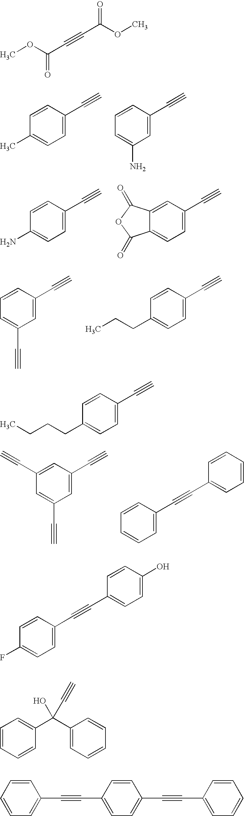
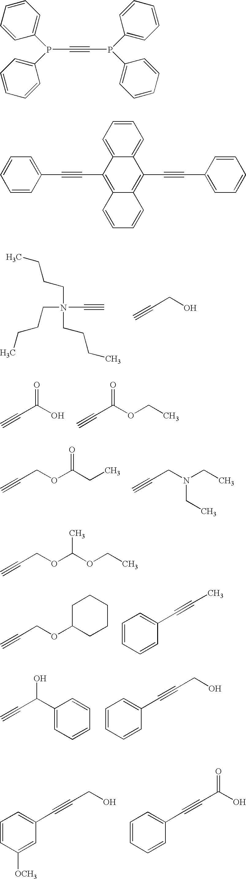
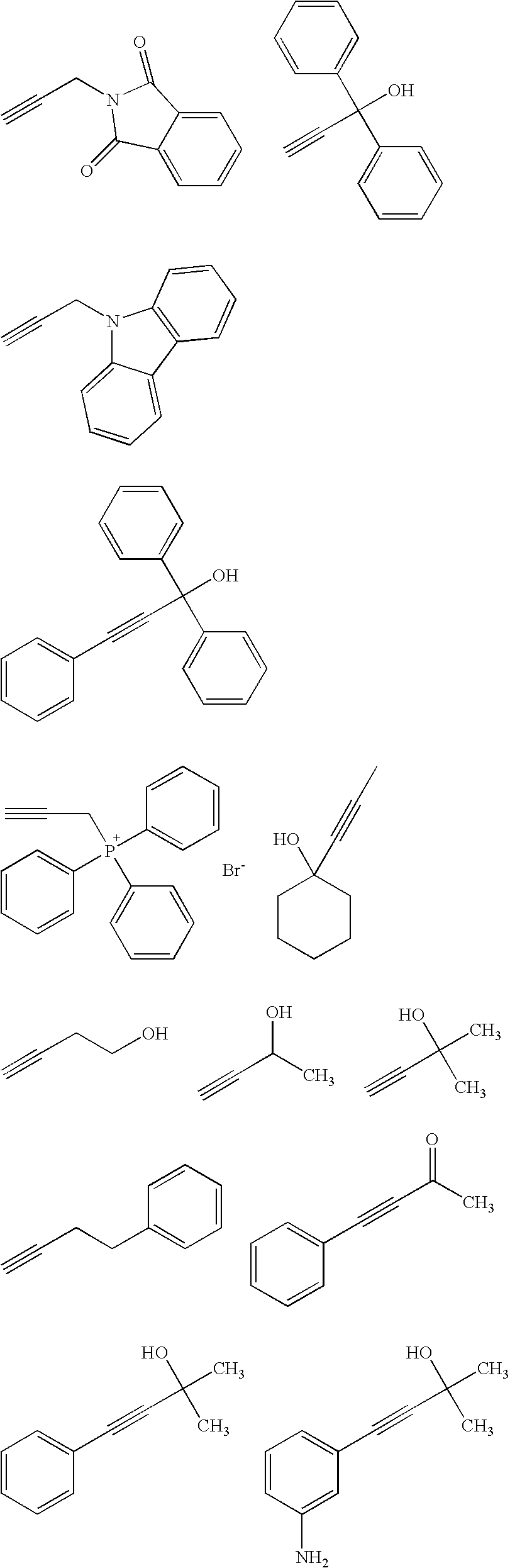
[0277]In a three-necked flask equipped with a stirring blade and a cooling tube, 3 parts by mass of AC-1 (an acetylene compound having the following structure, manufactured by Wako Pure Chemical Industries, Ltd.), 54 parts by mass of GOHSENAL T-215 (a PVA derivative, manufactured by Nippon Synthetic Chemical Industry Co., Ltd.) as a binder polymer, 1 part by mass of KETJENBLACK EC600JD (carbon black, manufactured by Lion Corporation) as a photothermal conversion agent, 20 parts by mass of diethylene glycol as a plasticizer, and 47 parts by mass of water as a solvent were placed, and the mixture was heated at 70° C. for 120 minutes while stirred, to dissolve the polymer. Furthermore, 25 parts by mass of an ethylenic unsaturated monomer, DPHA (dipentaerythritol hexaacrylate, manufactured by Toagosei Co., Ltd.), as a polymerizable compound, and 1.6 parts by mass of PERCUMYL D (a polymerization initiator, manufac...

examples 2 to 4

[0283]1. Preparation of Crosslinkable Resin Composition for Laser Engraving

[0284]Coating solutions for crosslinkable relief forming layer 2 to 4 (crosslinkable resin compositions for laser engraving) were prepared in the same manner as in Example 1, except that 3 parts by mass of “AC-1” used as an acetylene compound in Example 1 was changed to 3 parts by mass of an acetylene compound as shown below.

[0285]Acetylene Compound

[0286]Example 2: AC-2 (having the following structure, manufactured by Wako Pure Chemical Industries, Ltd.)

[0287]Example 3: AC-3 (having the following structure, manufactured by Wako Pure Chemical Industries, Ltd.)

[0288]Example 4: AC-4 (having the following structure, manufactured by Wako Pure Chemical Industries, Ltd.)

2. Production of Relief Printing Plate Precursor for Laser Engraving

[0289]Relief printing plate precursors for laser engraving 2 to 4 were obtained in the same manner as in Example 1, except that the coating solution for crosslinkable relief forming ...

example 5

1. Preparation of Crosslinkable Resin Composition for Laser Engraving

[0292]A coating solution for crosslinkable relief forming layer 5 was prepared in the same manner as in Example 1, except that 25 parts by mass of “DPHA” used as a polymerizable compound in Example 1 was changed to a monomer having the following structure.

2. Production of Relief Printing Plate Precursor for Laser Engraving

[0293]A relief printing plate precursor for laser engraving 5 was obtained in the same manner as in Example 1, except that the coating solution for crosslinkable relief forming layer 1 in Example 1 was changed to a coating solution for crosslinkable relief forming layer 5.

3. Production of Relief Printing Plate

[0294]A relief printing plate 5 was obtained in the same manner as in Example 1, by thermally crosslinking the relief forming layer of the relief printing plate precursor for laser engraving 5, and then performing engraving to form a relief layer.

[0295]The thickness of the relief layer of the...


PUM

PropertyMeasurementUnit
wavelength rangeaaaaaaaaaa
thicknessaaaaaaaaaa
thicknessaaaaaaaaaa

Abstract

The present invention provides a resin composition for laser engraving containing at least an acetylene compound and a binder polymer, a relief printing plate precursor for laser engraving using the same, a relief printing plate, and a method for producing a relief printing plate.

Description

CROSS-REFERENCE TO RELATED APPLICATION[0001]This application claims priority under 35 USC 119from Japanese Patent Application No. 2008-017882, the disclosure of which is incorporated by reference herein.BACKGROUND OF THE INVENTION[0002]1. Field of the Invention[0003]The present invention relates to a resin composition for laser engraving, a relief printing plate precursor for laser engraving, a relief printing plate, and a method of producing a relief printing plate.[0004]2. Description of the Related Art[0005]As a method for forming a printing plate by forming a concave-convex structure on a photosensitive resin layer laminated on the surface of a support, a method of exposing a relief forming layer which has been formed using a photosensitive composition, to ultraviolet radiation through an original image film so as to selectively cure image areas, and removing uncured parts by means of a developer solution, that is, so-called “analogue plate making”, is well known.[0006]A relief ...

Claims


Application Information

Patent Timeline
Patent Type & Authority Applications(United States)
IPC IPC(8): G03F7/004G03F1/02G03F1/88
CPCB41C1/05B41N1/12B41M5/24
Inventor SUGASAKI, ATSUSHI
Owner FUJIFILM CORP
Why Eureka
Try Eureka