Flying Foam Apparatus and Method of Making Flying Foam

a technology of flying foam and apparatus, which is applied in the field of flying foam apparatus and method of making flying foam, can solve the problems of undesirable low expansion foam incorporation into flying foam, and the inability to capture gas in sufficient quantities in order to achieve the desired lifting effect,

Inactive Publication Date: 2009-08-06
GUERRA FRANCISCO +1
View PDF7 Cites 5 Cited by
  • Summary
  • Abstract
  • Description
  • Claims
  • Application Information

AI Technical Summary

Benefits of technology

[0012]The present invention also includes the ability to produce a flammable foam shape. Flammable foam would be accomplished by utilizing a flammable gas as the lighter than air gas. The flammable gases may include but would not be limited to methane, acetylene, ethylene, and hydrogen. The flammable foam may then be ignited by any ignition source as is commonly known. The pyrotechnic and fireworks industry utilize wireless ignition, and chemical ignition techniques that include but would not be limited to nichrome wire and potassium chlorate. Flammable foam may produce a prominent visual effect at night where the flammable foam is set against a dark night sky.

Problems solved by technology

Low expansion foam is undesirable for incorporation into flying foam.
Low expansion foam does not entrap sufficient gas in order to produce the desired lifting effect.

Method used


Image

  • Flying Foam Apparatus and Method of Making Flying Foam
  • Flying Foam Apparatus and Method of Making Flying Foam
  • Flying Foam Apparatus and Method of Making Flying Foam

Examples


Embodiment Construction

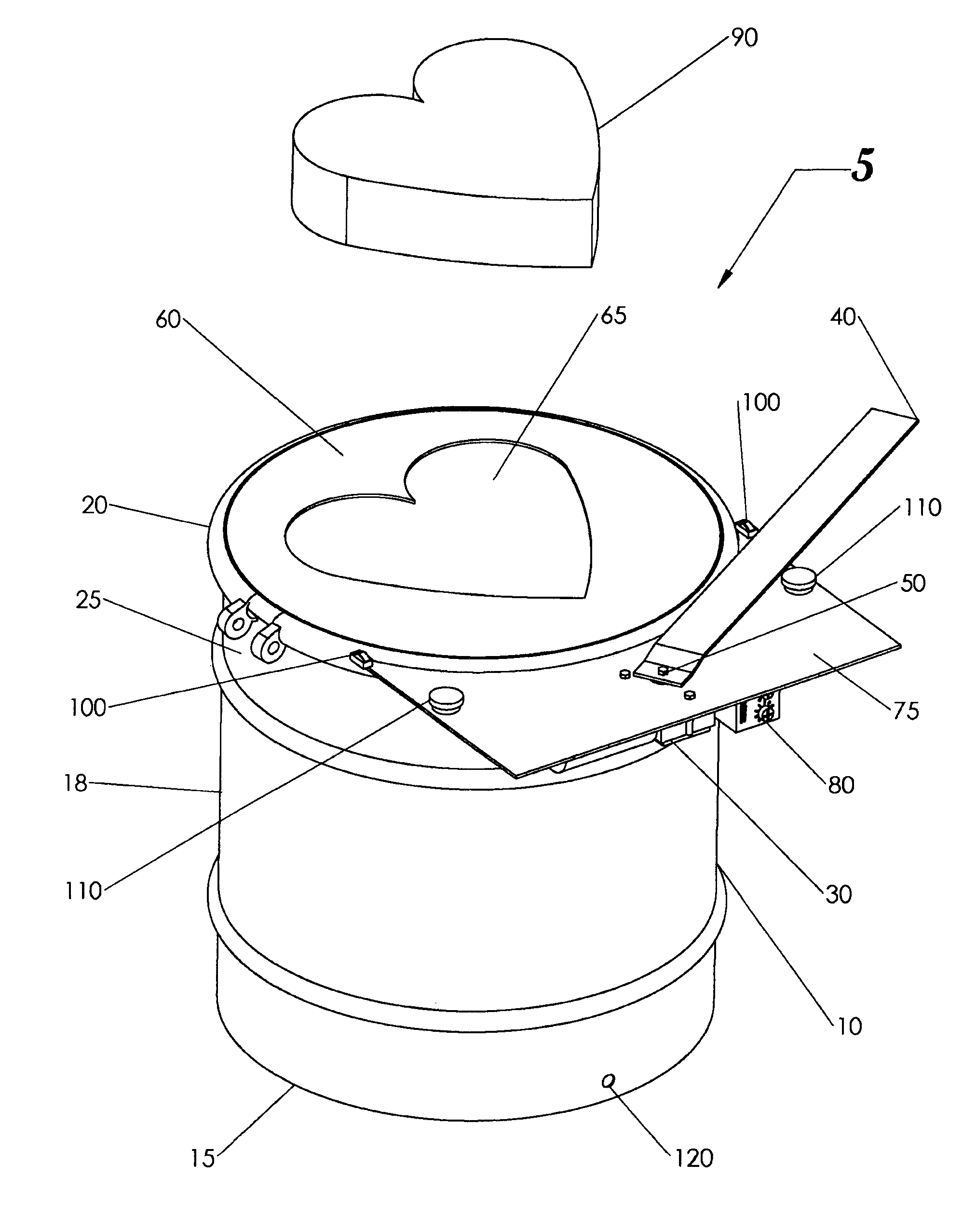
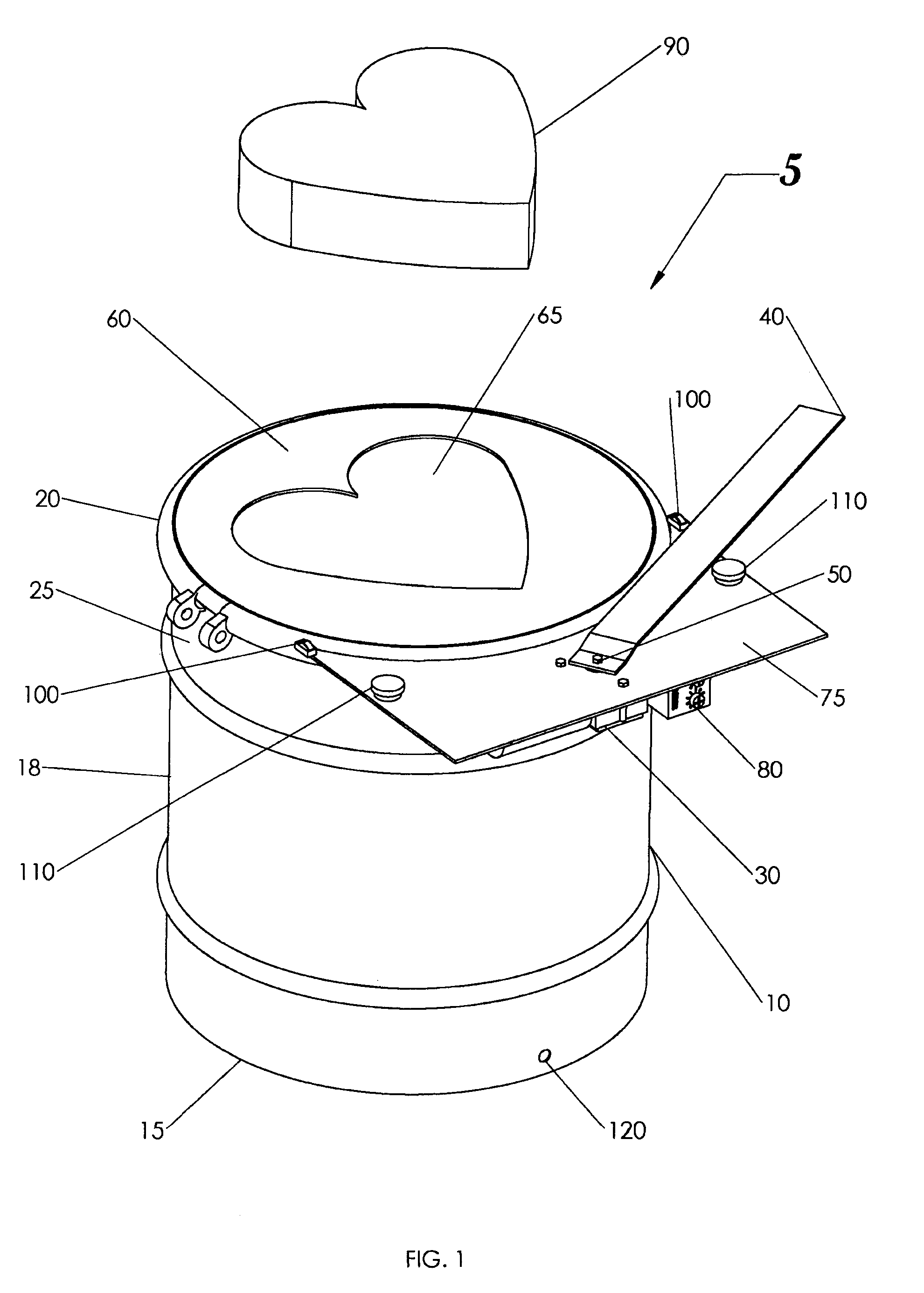
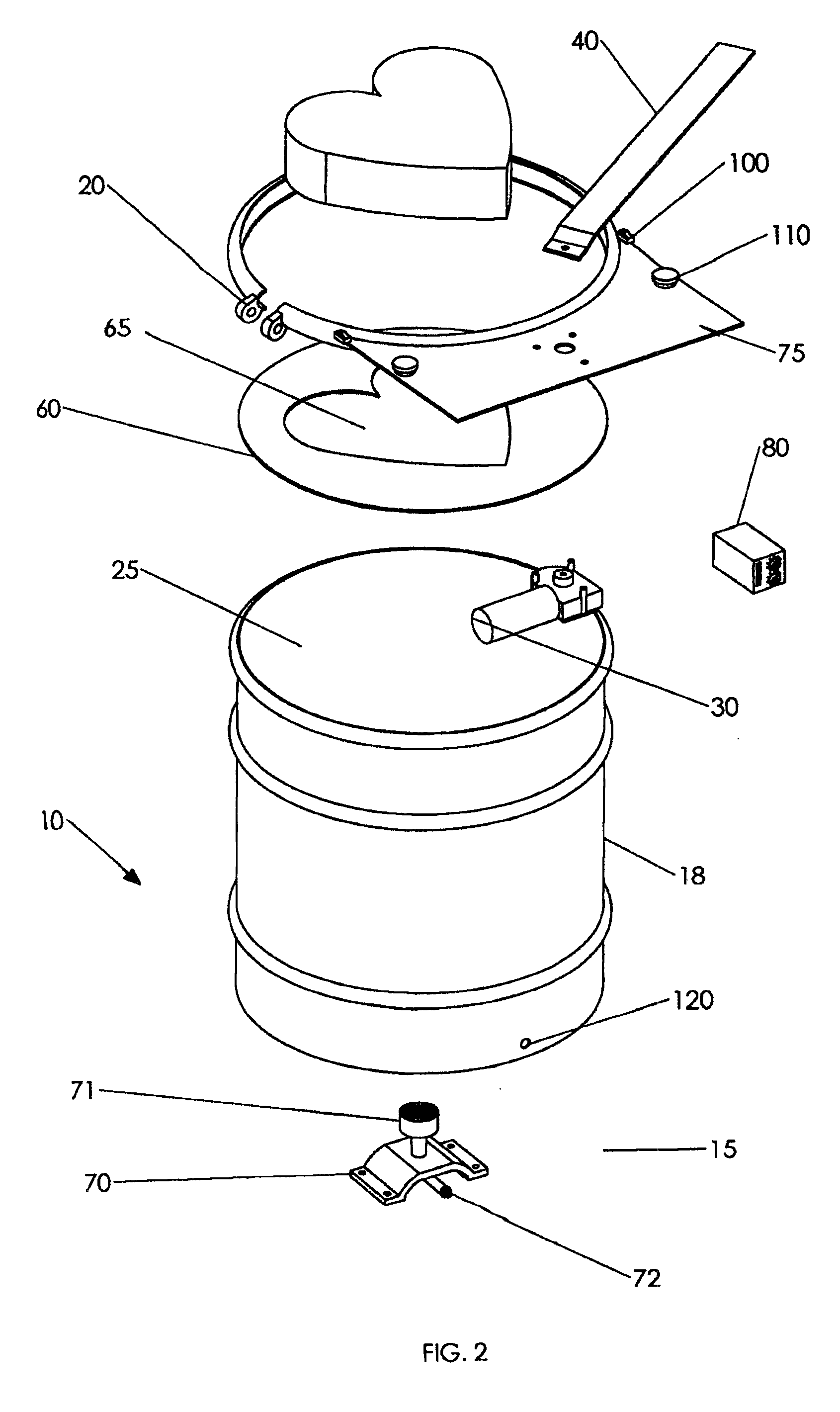
[0027]The present invention includes a flying foam assembly 5 having solution tank 10 that has an open end 25. Open end 25 receives logo board 60 that is removably attached to tank 10 with mounting ring 20. Tank 10 has a circumferal vertical side 18 that is substantially perpendicular to tank base 15. Logo board 60 is removed by detaching mounting ring 20 in order to add foam solution into tank 10.

[0028]Mounting ring 20 further incorporates cutting arm assembly 75 that is circumferally attached to mounting ring 20. Cutting arm assembly 75 has cutting arm 40 that moves about pivot 50. Pivot 50 is connected to motor 30 which further is incorporated with timer 80. Motor 30 electronically moves cutting arm 40 across the upper planar surface of logo board 60. Further incorporated onto cutting arm assembly 75 is a pair of bump stop protrusions 110 that limit the motion of cutting arm 40. Limit switch 100 is electronically connected to motor 30. When cutting arm 40 contacts limit switch 10...


PUM

PropertyMeasurementUnit
pressureaaaaaaaaaa
diameteraaaaaaaaaa
distanceaaaaaaaaaa

Abstract

The present invention is an apparatus for generating foam shapes that float in air having a container, a gas source, an aeration nozzle for aerating a gas from the gas source, an outlet, and a separator for separating extruded foam into individualized foam shapes.

Description

INDEX TO RELATED APPLICATIONS[0001]This application is a continuation-in-part of U.S. patent application Ser. No. 12 / 026,006, filed Feb. 5, 2008, the disclosure of which is incorporated herein by reference in its entirety.BRIEF SUMMARY OF THE INVENTION[0002]The present invention relates to an apparatus for producing floating foam shapes and a method of advertising using floating foam shapes.[0003]In order for foam to achieve flight, the overall mass of a given volume of foam must be less than the air it is displacing (Archimedes principle). It is desirable to have foam with a large bubble size. Large bubble size foam has water to surfactant percentage of 86% or less, and an expansion ratio of more than 200. Larger sized bubbles within the foam hold more gas, and hence have more lift. Tightly packed foam, also called low expansion foam, has small sized bubbles.[0004]One example of low expansion foam is shaving cream. Low expansion foam is undesirable for incorporation into flying foa...

Claims


Application Information

Patent Timeline
Patent Type & Authority Applications(United States)
IPC IPC(8): G09F21/06B29C44/20
CPCA63H33/28A63H2027/1025A63H2027/1075G09F19/00B29C47/0019G06Q99/00B29C47/00B29C48/00B29C48/07G09F21/06
Inventor GUERRA, FRANCISCOGLOVER, BRIAN
Owner GUERRA FRANCISCO
Why Eureka
Try Eureka