Laminated core, method and apparatus for manufacturing laminated core, and stator

a technology of laminated cores and stators, which is applied in the manufacture of stators/rotor bodies, magnetic circuit shapes/forms/construction, manufacturing tools, etc., can solve the problems of short circuits, degradation of the magnetic properties of laminated cores, and drawbacks of conventional manufacturing methods of laminated cores, etc., to achieve high productivity, stable bonding accuracy and bond strength, and high efficiency

Active Publication Date: 2009-08-06
MITSUBISHI ELECTRIC CORP
View PDF6 Cites 22 Cited by
  • Summary
  • Abstract
  • Description
  • Claims
  • Application Information

AI Technical Summary

Benefits of technology

[0016]The present invention is intended to overcome the aforementioned problems of the prior art. Accordingly, it is an object of the invention to provide a laminated core and a stator which make it unnecessary to swage core members, apply an adhesive theret...

Problems solved by technology

In this connection, recent arguments have focused on drawbacks of the conventional manufacturing methods of laminated cores.
This conventional method has a problem that the core members are deformed in areas around the protruding and recessed parts pressurized so that a dielectric coating formed on electromagnetic steel sheets could break, thereby causing short circuits between the laminated core members and resultant degradation of magnetic property of the laminated core.
This problem has been a bottleneck in increasing the efficiency of the equipment using motors.
Although there is a known technique for reduce eddy current by laminating a larger number of thin-walled core members to improve the magnetic property, this approach poses a problem that it difficult to form the protruding and recessed parts on the thin-walled core members.
Also because swaged portions of the core members are joined simply by press-fitting the protruding parts into the recessed parts, not all of the laminated core members are perfectly fixed together but gaps may be created between some of the core members.
Consequently, there has been a problem that the laminated core could produce noise when used due to relative movements of the core members.
This approach however causes a loss of cost and an environmental problem, because, in the manufacture of the laminated core, a steel sheet coated with a thermosetting resin adhesive at the steel sheet manufacturer is press-cut and unused part of the steel sheet trimmed away therefrom is discarded together with the adhesive coating.
When the laminated core manufacturer applies the adhesive as in the case of Japanese Patent No. 3822020, for example, there can o...

Method used


Image

  • Laminated core, method and apparatus for manufacturing laminated core, and stator
  • Laminated core, method and apparatus for manufacturing laminated core, and stator
  • Laminated core, method and apparatus for manufacturing laminated core, and stator

Examples


first embodiment

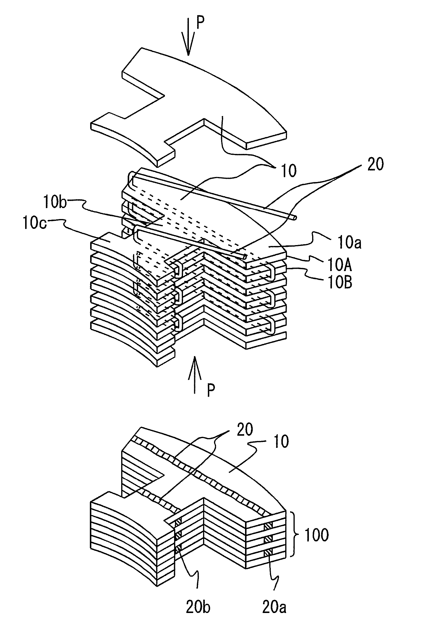
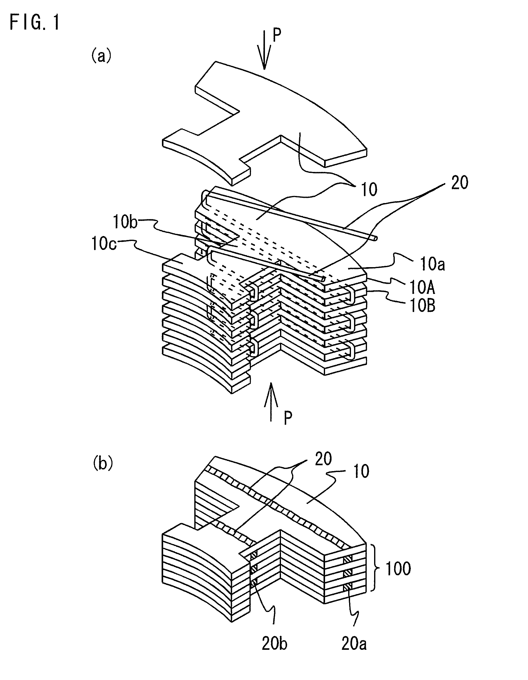
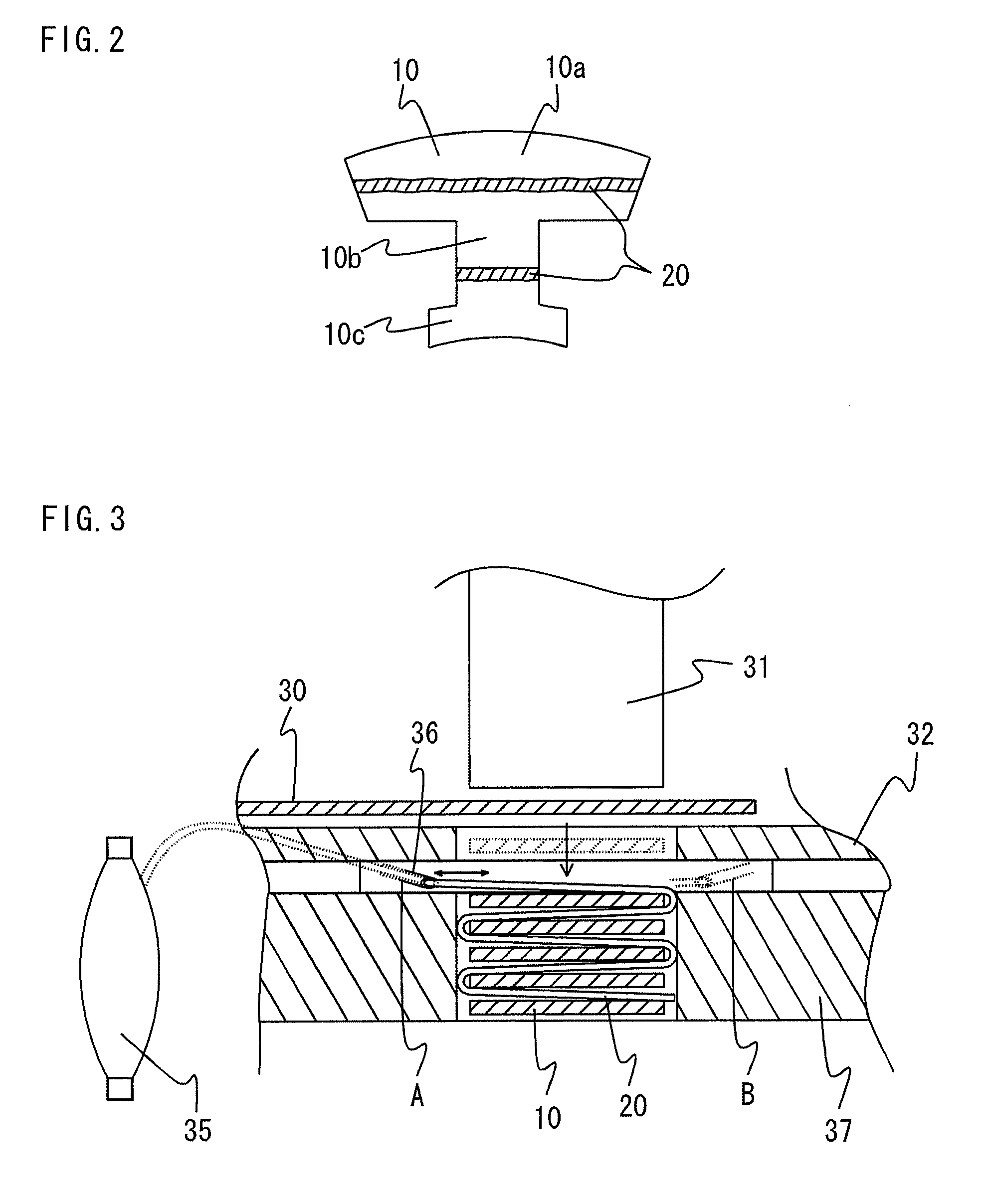
[0037]FIGS. 1A and 1B are perspective views showing the structure of a laminated core block 100 according to a first embodiment of the invention, in which FIG. 1A depicts a state before a laminating process and FIG. 1B depicts a state after the laminating process. FIG. 2 is a plan view showing an arrangement made between individual core members 10 of the laminated core block 100 of FIGS. 1A and 1B. As shown in these Figures, the laminated core block 100 is constructed by laminating a plurality of core members 10 which are magnetic sheets like iron sheets or electromagnetic steel sheets measuring approximately 1 mm or less in thickness. Each of the core members 10 has generally a T-shape including a yoke portion 10a, a tooth portion 10b extending from the yoke portion 10a and a tooth end portion 10c located at a far end of the tooth portion 10b.

[0038]In this embodiment, a threadlike thermoplastic resin strand 20 is placed between the individual core members 10 to run side to side ac...

second embodiment

[0048]While the foregoing discussion of the first embodiment has described the arrangement in which the thermoplastic resin strand 20 is laid in the direction generally at right angles to the projecting direction of the tooth portion 10b of each core member 10, this arrangement may be so modified that the thermoplastic resin strand 20 runs across the tooth portion 10b of each core member 10 in a direction generally parallel to the projecting direction of the yoke portion 10a along two lines located generally symmetrically about a center line of the tooth portion 10b according to the present invention.

[0049]FIG. 5 is a plan view showing the structure of a laminated core block 100 according to a second embodiment of the invention. In this embodiment, the thermoplastic resin strand 20 is arranged between the individual core members 10 to run across the tooth portion 10b of each core member 10 in the direction generally at right angles to the projecting direction of the tooth portion 10...

third embodiment

[0053]While the thermoplastic resin strand 20 is laid in the direction generally at right angles to or generally parallel to the projecting direction of the tooth portion 10b of each core member 10 in the foregoing embodiments, two sections of the thermoplastic resin strand 20 may be arranged to be folded back between the outer peripheral side of the yoke portion 10a of each core member 10 and both circumferential ends thereof generally symmetrically at two locations.

[0054]FIG. 8 is a plan view showing the structure of a laminated core block 100 according to a third embodiment of the invention. As depicted in FIG. 8, the yoke portion 10a of each core member 10 has a pair of cut-out parts 60 formed in the outer peripheral side of the yoke portion 10a opposite to the tooth portion 10b generally symmetrically about a center line thereof. Each core member 10 further has a recessed part 41 formed in one side surface of the yoke portion 10a and a protruding part 42 formed on the opposite ...


PUM

PropertyMeasurementUnit
Angleaaaaaaaaaa

Abstract

A laminated core block includes a plurality of core members made of magnetic sheets stacked one on top of another, the plurality of core members including first and second core members which adjoin in a laminating direction, and a thermoplastic resin strand placed between the first and second core members. The thermoplastic resin strand is arranged to pass along one side surface of the first core member, between the first and second core members and along a side surface of the second core member on a side opposite to the aforementioned side surface of the first core member in this order. The first and second core members are bonded to each other by melting and curing the thermoplastic resin strand.

Description

BACKGROUND OF THE INVENTION[0001]1. Field of the Invention[0002]The present invention relates to a laminated core used in a motor, a generator, a transformer, or the like, the laminated core being configured by laminating core members which are made of magnetic sheets. The invention relates also to a method and an apparatus for manufacturing a laminated core as well as a stator employing the laminated core.[0003]2. Description of the Background Art[0004]A conventional method of manufacturing a laminated core uses a punch swaging process in which core members are laminated as the same are punched from a beltlike thin sheet and swaged together. In the punch swaging process, thicknesswise protruding and recessed parts are formed in the individual core members with the protruding part formed on a front side of each core member and the recessed part formed in a rear side thereof, for example, and when a plurality of such core members are laminated, the core members are fixed one on top o...

Claims


Application Information

Patent Timeline
IPC IPC(8): H02K1/18H02K15/02
CPCH02K1/08H02K15/022Y10T29/49009Y10T29/53143Y10T156/12
Inventor MIYAKE, NOBUAKINAKAHARA, YUJIYUYA, MASAHIROKARATA, YUKINOBUHASHIMOTO, AKIRA
Owner MITSUBISHI ELECTRIC CORP
Why Eureka
Try Eureka