Motor control system including electrical insulation deterioration detecting system

a technology of motor control system and detection system, which is applied in the direction of motor/generator/converter stopper, dynamo-electric converter control, instruments, etc., can solve the problems of motor wetness, failure of a system using the motor, and the electrical insulation of the motor may accordingly be deteriorated, so as to reduce the number of components required for detection, such as switches, and achieve high precision. , the effect of reducing the cos

Active Publication Date: 2009-08-06
SANYO DENKI CO LTD
View PDF4 Cites 41 Cited by
  • Summary
  • Abstract
  • Description
  • Claims
  • Application Information

AI Technical Summary

Benefits of technology

[0034]Since the voltage divider circuit serves as a resistance load against the motor and the smoothing capacitor upon detecting the electrical insulation deterioration, overcurrent does not flow from the smoothing capacitor during a short time period trough the semiconductor switch in conductive state, even when the motor is ground faulted. Accordingly, the semiconductor switch included in the inverter circuit can be prevented from being damaged even when the motor is ground faulted.
[0035]Upon detection, since the electrical insulation deterioration is detected by applying a direct current to a circuit including the semiconductor switches with the use of the smoothing capacitor as an operation power supply for detection, electrical insulation deterioration can be detected with high precision without being affected by stray capacitances of the motor and wiring cable.
[0036]Since the deterioration state of the electrical insulation resistance can be detected for a plurality of motors driven by a plurality of inverter circuits simply by using one electrical insulation deterioration detecting system, electrical insulation deterioration can be detected for the plurality of motors at lower cost.
[0037]In particular in the present invention, since some of the semiconductor switches included in the inverter circuit and put into conductive state are used to detect the electrical insulation deterioration, the number of components required for detection, such as a switch, can be reduced. If an alarm signal is detected when placing the plurality of semiconductor switches into a conductive state one by one in a predetermined sequence, it becomes possible to know not only a possibility of occurrence of deterioration in the electrical insulation resistance of a motor but also to know a possibility of electrical insulation deterioration in the excitation winding of the motor to which the semiconductor switch in the conductive state is connected, thereby identifying the cause of the electrical insulation deterioration.

Problems solved by technology

If the machine tool uses a cutting fluid, the motor may get wet with the cutting fluid and the cutting water may enter the motor.
The electrical insulation of the motor may accordingly be deteriorated.
The electrical insulation deterioration of the motor is progressing gradually and finally results in a ground fault.
The ground fault of motor may cause an earth leakage circuit to trip and damage the motor control system, which may result in a failure of a system using the motor.
The system failure exerts great influence on the production line of a factory.
However, this method requires many man-hours for removing wiring of the motor.
However, in the motor control system including the PWM controlled inverter circuit, since leakage current flows through the power supply due to a switching operation of semiconductor devices included in the inverter circuit, it is difficult to properly detect the electrical insulation deterioration of the motor.
In the above-mentioned method (3), since current flowing through the detection circuit is affected by a leakage current flowing through a power supply or flowing through stray capacitances of a motor and a wiring cable, a detection error is likely to occur in detecting the electrical insulation deterioration.
In this method, however, if the electrical insulation of the motor is deteriorated and the ground fault has occurred, the direct current voltage of the inverter circuit may be short-circuited when the semiconductor devices included in the inverter circuit are in a conductive state.
As a result, the semiconductor devices may be damaged.
However, an ordinary current detector cannot obtain such high detecting accuracy, and it is difficult to increase the detecting accuracy of an ordinary current detector.
Further, it is difficult o know the cause of the electrical insulation deterioration of a motor by the conventional methods.

Method used


Image

  • Motor control system including electrical insulation deterioration detecting system
  • Motor control system including electrical insulation deterioration detecting system
  • Motor control system including electrical insulation deterioration detecting system

Examples


Embodiment Construction

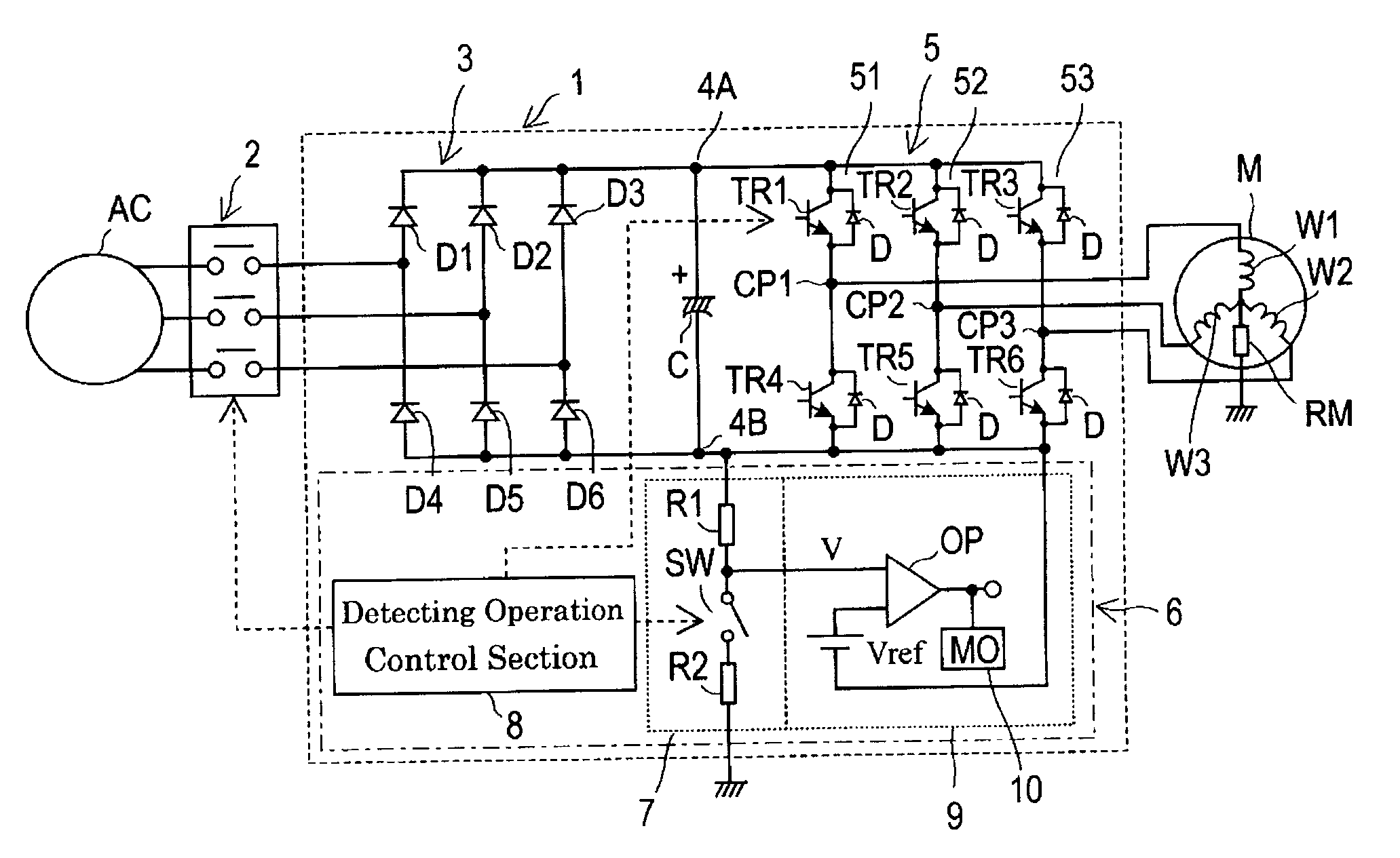
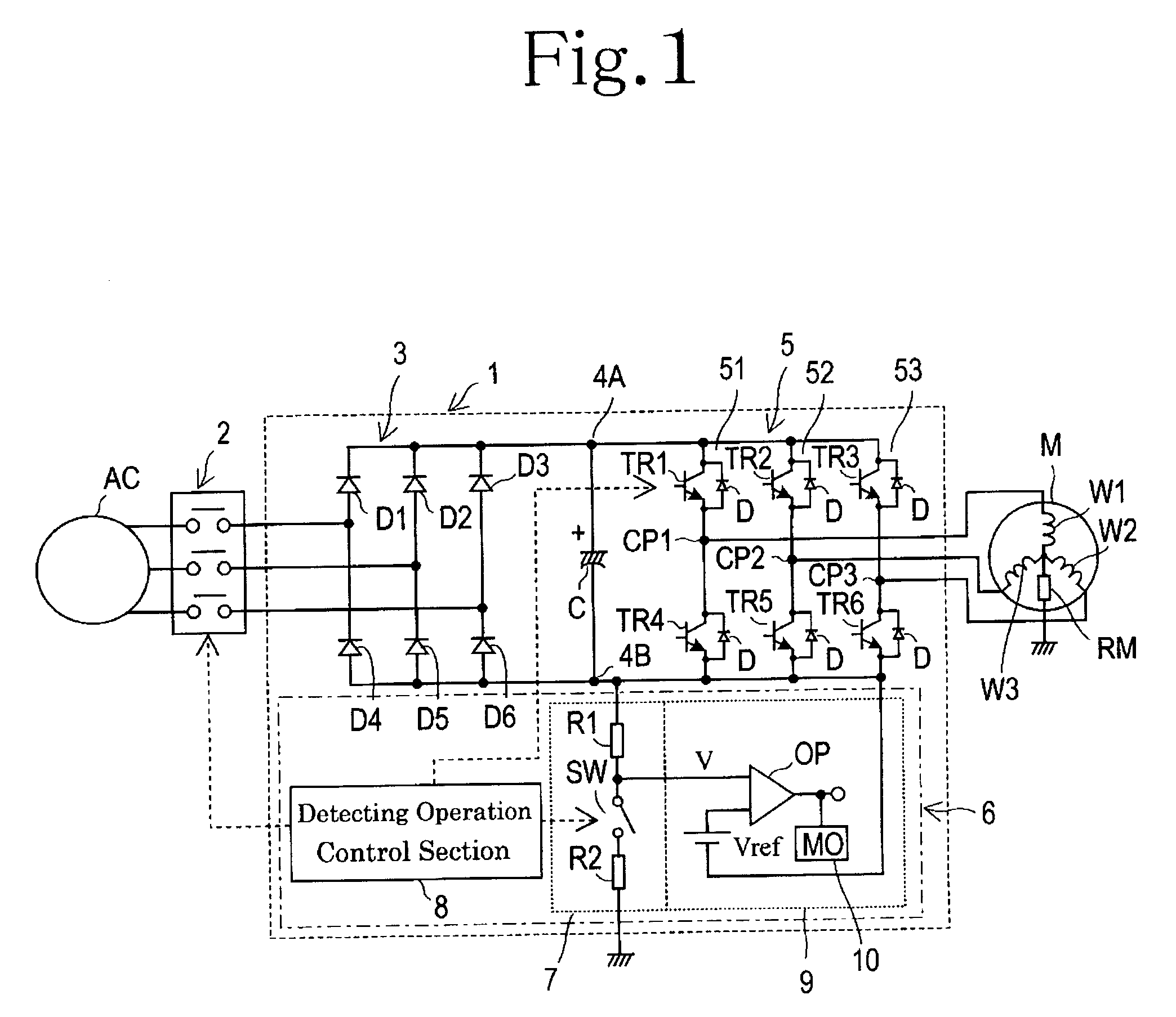
[0041]Embodiments of the present invention for carrying out a motor control system and a method of detecting electrical insulation deterioration of a motor will now be described in detail hereinbelow with reference to the accompanying drawings. FIG. 1 shows an example configuration of a motor control system 1, in which one three-phase motor M is driven by one inverter circuit 5. The motor control system 1 is connected to a three phase alternating current power supply AC through an electromagnetic contactor 2 that serves as a circuit breaker. In the motor control system 1, three phase alternating currents outputted from the three phase alternating current power supply AC are fully rectified through a full wave rectifier circuit 3, which is constituted from a bridge connection of the six diodes D1 to D6 so that a direct current voltage may be obtained. The direct current voltage is then smoothed by a smoothing capacitor C, which is constituted from an electrolytic capacitor. In the pr...


PUM


Abstract

A motor control system of the present invention includes an accurate electrical insulation deterioration detecting system. A voltage divider circuit is arranged between a negative DC output portion and a ground, through a normally open switch circuit. A detecting operation control section closes the normally open switch while a circuit breaker is opened, and places at least one of transistors electrically connected to a positive DC output portion into a conductive state, from among six transistors included in three arm circuits. A voltage across the first resistor is inputted as a divided voltage into a voltage comparator of a voltage comparison section. The voltage comparison section compares a divided voltage outputted from the voltage divider circuit and a reference voltage using the voltage comparator and outputs an alarm signal if the divided voltage exceeds the reference voltage.

Description

BACKFIELD OF THE INVENTION[0001]The present invention relates to a motor control system including an electrical insulation deterioration detecting system which detects the electrical insulation deterioration (an unusual decrease of electrical insulation resistance) of a motor and a method of detecting the electrical insulation deterioration of the motor.BACKGROUND OF THE INVENTION[0002]Various kinds of motors, such as a servo motor used with a machine tool etc., are driven by a motor control system including a PWM controlled inverter circuit. If the machine tool uses a cutting fluid, the motor may get wet with the cutting fluid and the cutting water may enter the motor. The electrical insulation of the motor may accordingly be deteriorated. The electrical insulation deterioration of the motor is progressing gradually and finally results in a ground fault. The ground fault of motor may cause an earth leakage circuit to trip and damage the motor control system, which may result in a f...

Claims


Application Information

Patent Timeline
Patent Type & Authority Applications(United States)
IPC IPC(8): G01R31/06
CPCG01R31/1227G01R31/346G01R31/343G01R31/34H02K11/00
Inventor IDE, YUJI
Owner SANYO DENKI CO LTD
Why Eureka
Try Eureka