Method and apparatus for cooling syngas within a gasifier system

a gasifier and syngas technology, applied in the field of synthesis gas or syngas coolers for use in the gasifier system, can solve the problems of large capital investment in such a two-syngas cooler arrangement that may not always be cost-effective, and cannot effectively mitigate fouling and plugging

Active Publication Date: 2009-08-13
AIR PROD & CHEM INC
View PDF10 Cites 55 Cited by
  • Summary
  • Abstract
  • Description
  • Claims
  • Application Information

AI Technical Summary

Benefits of technology

[0004]In one aspect, a method of assembling a synthesis gas (syngas) cooler for a gasification system is provided. The method includes positioning a dip tube within a shell of the syngas cooler. The dip tube is configured to at least one of at least partially quench at least a portion of the syngas flowing through the shell and at least partially channel at least a portion of the syngas through the dip tube. The method also includes coupling an isolation tube to the dip tube such that the isolation tube is s

Problems solved by technology

Such a series cooler arrangement facilitates heat transfer efficiency, however, a large capital investment in such a two syngas cooler arrangement may not always be cost-effective.
Furthermore, under certain circumstances, such an arrangement may not effectively mitigate fouling and plugging.
However, incorporating

Method used


Image

  • Method and apparatus for cooling syngas within a gasifier system
  • Method and apparatus for cooling syngas within a gasifier system
  • Method and apparatus for cooling syngas within a gasifier system

Examples


Embodiment Construction

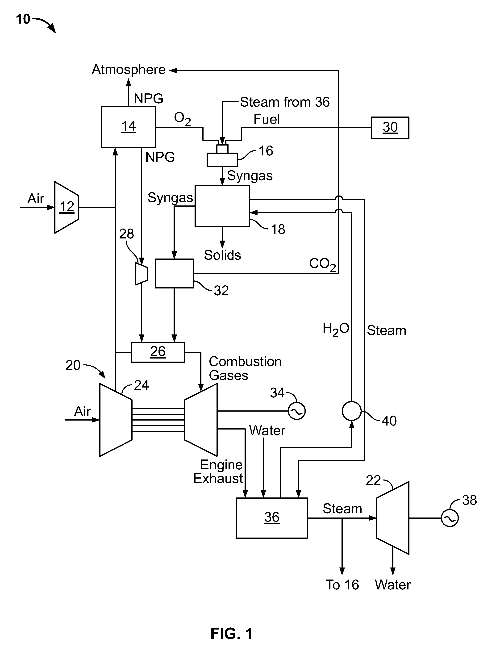
[0010]FIG. 1 is a schematic diagram of an exemplary integrated gasification combined-cycle (IGCC) power generation system 10. IGCC system 10 generally includes a main air compressor 12, an air separation unit (ASU) 14 coupled in flow communication to compressor 12, a gasifier 16 coupled in flow communication to ASU 14, a syngas cooler 18 coupled in flow communication to gasifier 16, a gas turbine engine 20 coupled in flow communication with syngas cooler 18, and a steam turbine engine 22 coupled in flow communication with syngas cooler 18.

[0011]In operation, compressor 12 compresses ambient air that is then channeled to ASU 14. In the exemplary embodiment, in addition to compressed air from compressor 12, compressed air from a gas turbine engine compressor 24 is supplied to ASU 14. Alternatively, compressed air from gas turbine engine compressor 24 is supplied to ASU 14, rather than compressed air from compressor 12 being supplied to ASU 14. In the exemplary embodiment, ASU 14 uses ...


PUM

PropertyMeasurementUnit
Pressureaaaaaaaaaa
Dynamicaaaaaaaaaa

Abstract

A method of assembling a synthesis gas (syngas) cooler for a gasification system includes positioning a dip tube within a shell of the syngas cooler. The dip tube is configured to quench the syngas flowing through the shell and/or at least partially channel the syngas through the dip tube. The method also includes coupling an isolation tube to the dip tube such that the isolation tube is substantially concentrically aligned with, and radially outward of, the dip tube. The isolation tube is coupled in flow communication with a purge gas source and is configured to at least partially form a dynamic pressure seal. The method further includes coupling at least one of the isolation tube and the dip tube in fluid communication with a fluid retention chamber. The method also include at least partially filling the fluid retention chamber with fluid, thereby further forming the dynamic pressure seal.

Description

BACKGROUND OF THE INVENTION[0001]This invention relates generally to synthesis gas, or syngas, coolers for use in a gasifier system, and, more specifically, to a quench system for use with a syngas cooler.[0002]Some known gasification systems use two syngas coolers in series to cool syngas, slag, and fly ash particles contained therein. Such systems can be used advantageously because, typically, a first syngas cooler, typically a radiant syngas cooler, or RSC, incorporates slag and fly ash separation and quenching means near a first syngas outlet that facilitates reducing the potential of fouling and plugging in a second syngas cooler. Fouling and plugging is a concern associated with the second syngas cooler, typically a convective syngas cooler, or CSC, due to changes in heat transfer surface materials and configurations that are used to effectively transfer heat, as well as changing flow conditions. Such a series cooler arrangement facilitates heat transfer efficiency, however, a...

Claims


Application Information

Patent Timeline
IPC IPC(8): C10J3/82C10J3/20B21D53/02B01J7/00
CPCC01B3/36Y10T29/4935C01B2203/0475C01B2203/049C01B2203/06C01B2203/0877C10J3/52C10J3/78C10J3/84C10J3/845C10J2200/09C10J2300/1653C10K1/101Y02E20/18C01B2203/0255
Inventor JIMENEZ-HUYKE, ALLYSON JOYSTOREY, JAMES MICHAELSTEVENSON, JOHN SAUNDERSAVAGLIANO, AARON JOHNLEININGER, THOMAS FREDERICKCORRY, JUDETH BRANNON
Owner AIR PROD & CHEM INC
Why Eureka
Try Eureka