Microstructure modification in copper interconnect structure

a microstructure and interconnect technology, applied in the field of metal interconnect structures, can solve the problems of non-bamboo microstructure of 90 nm copper interconnect technology, line failure, constraint on the design and layout of interconnect structures, etc., and achieve the effect of avoiding copper diffusion through grain boundaries and speeding up the ra

Active Publication Date: 2009-08-20
TESSERA INC
View PDF13 Cites 46 Cited by
  • Summary
  • Abstract
  • Description
  • Claims
  • Application Information

AI Technical Summary

Benefits of technology

[0012]The present invention incorporates cobalt into a copper interconnect structure in order to modify the microstructure to achieve bamboo-style grain boundaries in sub-90 nm technologies. Preferably, bamboo grains are separated at distances less than the “Blech” length so that copper diffusion through grain boundaries is avoided. The cobalt can be incorporated into a copper seed layer to be formed under a metal line, as a capping layer to be formed over a metal line, or during

Problems solved by technology

Current sub-90 nm copper interconnect technology suffers from a non-bamboo microstructure, i.e., a microstructure without bamboo-like features, in lines and vias.
This leads to problems associated with copper diffusion such as electromigration and stress voiding.
This drift eventually will lead to line failure due to loss of copper at divergent sites such as grain boundaries and material interfaces.
While, in principle, designing all interconnect metal line

Method used


Image

  • Microstructure modification in copper interconnect structure
  • Microstructure modification in copper interconnect structure
  • Microstructure modification in copper interconnect structure

Examples


Embodiment Construction

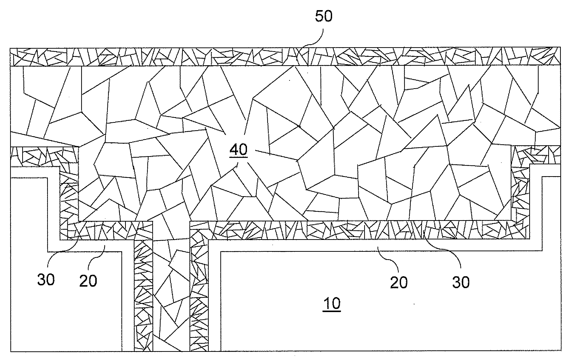
[0068]As stated above, the present invention relates to metal interconnect structures having large grain sizes at a bottom of a metal interconnect line and methods of manufacturing the same, which are now described in detail with accompanying figures. It is noted that like and corresponding elements are referred to by like reference numerals.

[0069]Referring to FIG. 4, a first exemplary metal interconnect structure according to a first embodiment of the present invention comprises a dielectric layer 10, a metallic barrier layer 20, a copper-cobalt alloy seed layer 30X, and a plated copper-containing layer 40. The dielectric layer 10 is typically formed on a semiconductor substrate (not shown) containing semiconductor devices (not shown). The dielectric layer 10 comprises a dielectric material such as silicon oxide, silicon nitride, organosilicate glass (OSG), SiCOH, a spin-on low-k dielectric material such as SiLK™, etc. The dielectric layer 10 may be porous, or non-porous. A via cav...


PUM


Abstract

Cobalt is added to a copper seed layer, a copper plating layer, or a copper capping layer in order to modify the microstructure of copper lines and vias. The cobalt can be in the form of a copper-cobalt alloy or as a very thin cobalt layer. The grain boundaries configured in bamboo microstructure in the inventive metal interconnect structure shut down copper grain boundary diffusion. The composition of the metal interconnect structure after grain growth contains from about 1 ppm to about 10% of cobalt in atomic concentration. Grain boundaries extend from a top surface of a copper-cobalt alloy line to a bottom surface of the copper-cobalt alloy line, and are separated from any other grain boundary by a distance greater than a width of the copper-cobalt alloy line.

Description

FIELD OF THE INVENTION[0001]The present invention relates to semiconductor structures, and particularly to metal interconnect structures having large grain sizes at a bottom of a metal interconnect line and methods of manufacturing the same.BACKGROUND OF THE INVENTION[0002]Current sub-90 nm copper interconnect technology suffers from a non-bamboo microstructure, i.e., a microstructure without bamboo-like features, in lines and vias. This leads to problems associated with copper diffusion such as electromigration and stress voiding.[0003]Three different modes of copper diffusion are known. The first mode is copper diffusion along grain boundaries of a copper interconnect structure. The second mode is copper diffusion at a surface of a copper interconnect structure, i.e., at an interface at which the copper interconnect structure adjoins another material. The third mode is copper bulk diffusion through grams, i.e., across an interface at which two grain boundaries meet. Typically, the...

Claims


Application Information

Patent Timeline
IPC IPC(8): H01L21/768H01L23/538
CPCH01L21/76873H01L23/53238H01L23/53233H01L21/76877H01L2924/0002H01L2924/00
Inventor BAKER-O'NEAL, BRETT C.CABRAL, JR., CYRILHUANG, QIANGRODBELL, KENNETH P.
Owner TESSERA INC
Why Eureka
Try Eureka