Heat tube device utilizing cold energy and application thereof

a technology of cold energy and heat tube, applied in the field of refrigerating system, can solve the problems of high operating cost, high product energy consumption, unstable operation, etc., and achieve the effect of low heat conducting coefficien

Inactive Publication Date: 2009-08-27
YIN XUEJUN
View PDF17 Cites 54 Cited by
  • Summary
  • Abstract
  • Description
  • Claims
  • Application Information

AI Technical Summary

Benefits of technology

[0014]At least one of a part of the evaporating tube, the ascending tube and the reflow tube has an insulating layer disposed outside of the tube wall, alternatively the tube wall is made of material having low heat conducting coefficient.

Problems solved by technology

It has the drawbacks of high product energy consumption, high operating cost, unstable operation, complicated maintenance, use of harmful medium, direct and indirect discharge of greenhouse gases and other contamination, noise pollution, strong dependence on electric power, and strong influence on electric power peak load.
But it has the following defects: (1) the input and output of cold energy is carried out by a large amount of commercial coolant, thus forced circulation is required at least for the output of cold energy, resulting in the low efficiency of the natural convection; (2) the input and output of cold energy both go through a secondary heat exchange, which will lower the efficiency of heat exchange and increase the loss of cold energy; (3) the air conduit can not eliminate loss of cold energy during conduction and convection; (4) the air conduit would be clogged; (5) the air and the steel tube wall have low efficiency of heat exchange, and a large amount of tubing and supports are required in real engineering; (6) the natural cold energy storage device satisfying the requirement of heat preservation, anti-expansion, anti-infiltration, and high efficiency of heat exchange is expensive, which is difficult to be put into practice.
Some of the current cold storing devices also use a single heat tube shown in FIG. 1 as the cold conducting element, but such storage apparatus with single heat tube still has the following defects: (1) the ascending vapor and descending coolant are in the same tube with circulation resistance occurred therebetween, causing an effect of heat exchange between each other, thus affecting the conducting power.
Therefore the single heat tube has small cold conducting power; (2) relatively higher manufacturing cost under the condition of same conducting power; (3) the assembling is limited by angle; (4) it can not achieve ordered freezing by switching on and off or adjusting the magnitude of power.

Method used


Image

  • Heat tube device utilizing cold energy and application thereof
  • Heat tube device utilizing cold energy and application thereof
  • Heat tube device utilizing cold energy and application thereof

Examples


embodiment 4

of the Heat Tube Device

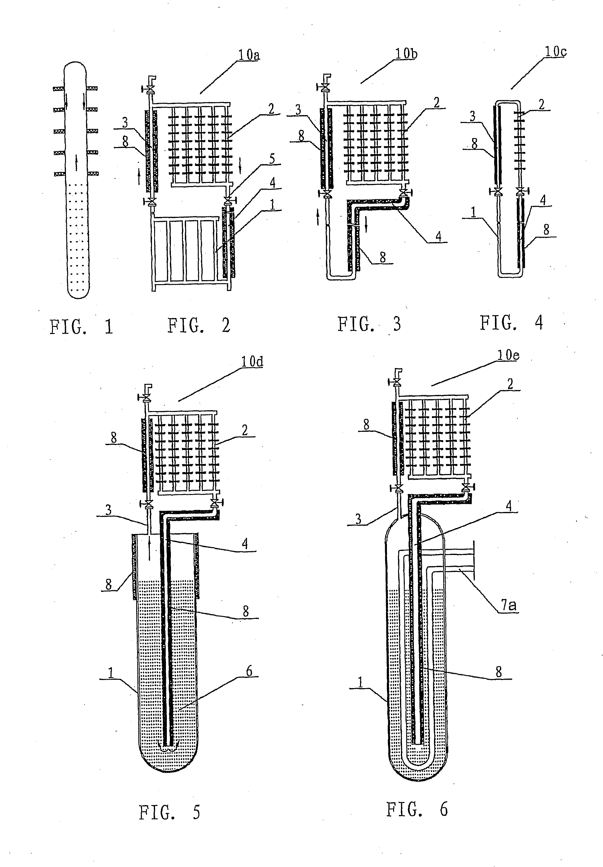
[0050]As shown in FIG. 5, the heat tube device 10d differs with respect to the embodiment 1 in that the evaporating part 1 is a thimble tube with the upper orifice thereof communicated with an ascending tube 3, and a reflow tube 4 being inserted into the lower portion of the cavity of the thimble tube. An insulating layer 8 is disposed on the ascending tube 3 and the reflow tube 4. The cavity of the thimble tube is filled with working substance 6 with a low boiling point.

[0051]When the temperature of the medium outside the evaporating part is not uniform, usually the surface layer has lower temperature, the evaporating tube with lower temperature may be provided with an insulating layer 8 at the upper section, so as to prevent heat energy from dissipating toward the medium outside the surface layer via the upper section of the evaporating tube, whereby improving the efficiency of heat conduction.

[0052]Compared with the preceding embodiments, the working substa...

embodiment 5

of the Heat Tube Device

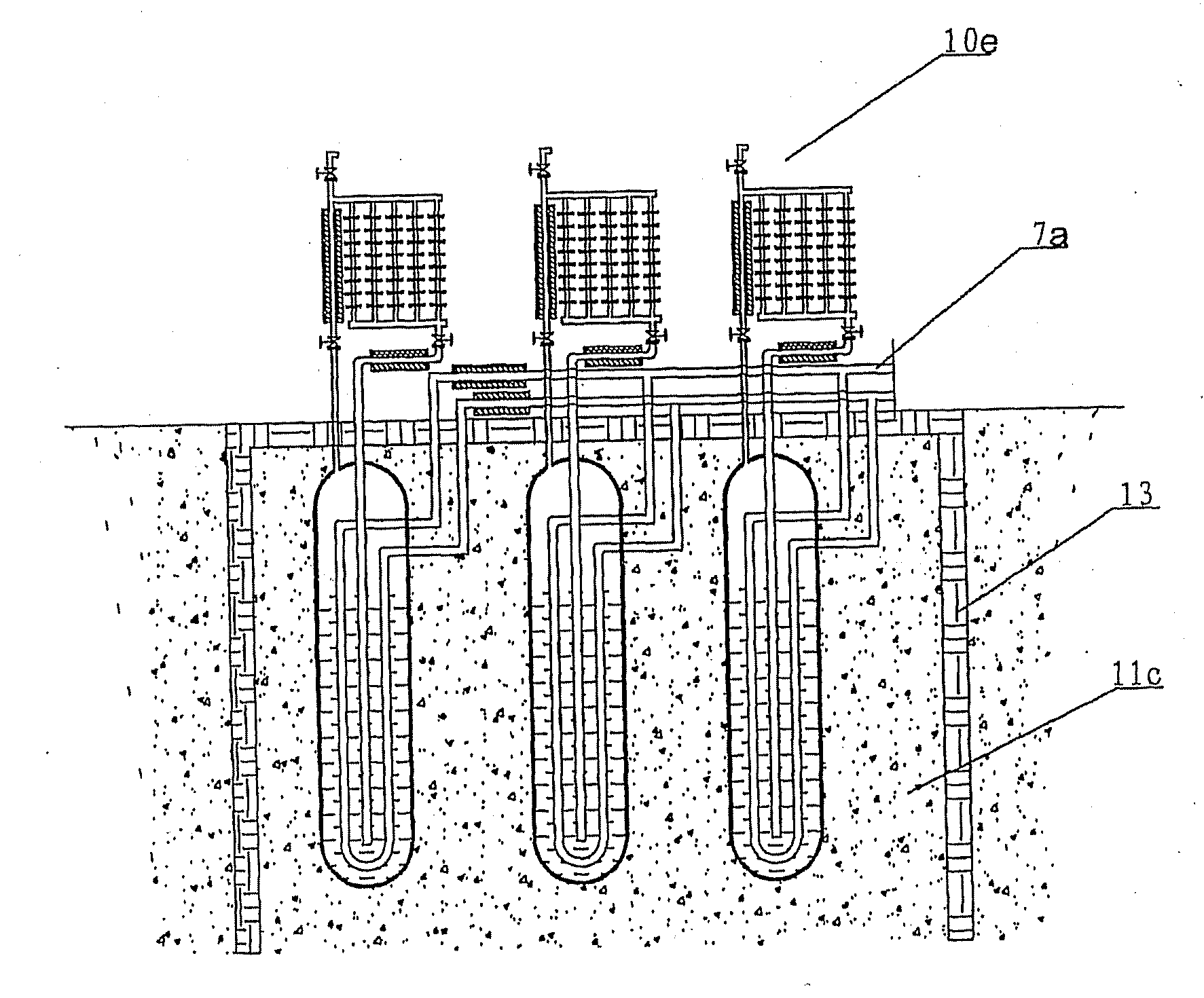
[0054]As shown in FIG. 6, the heat tube device 10e is different with respect to the embodiment 4 in that a power cycle tube 7a is disposed inside the thimble tube of the evaporating part 1, the inlet and outlet of the power cycle tube 7a being positioned out of the evaporating part 1. An insulating layer 8 is disposed on an ascending tube 3 and a reflow tube.

[0055]Compared with the preceding embodiments, which may realize upwards one-way heat conduction and downwards one-way cold conduction but can not realize reverse conduction, the present embodiment can realize heat and cold conduction in any direction and with ultra deep and long distance by pumping power since it is integrated with the power cycle tube 7a.

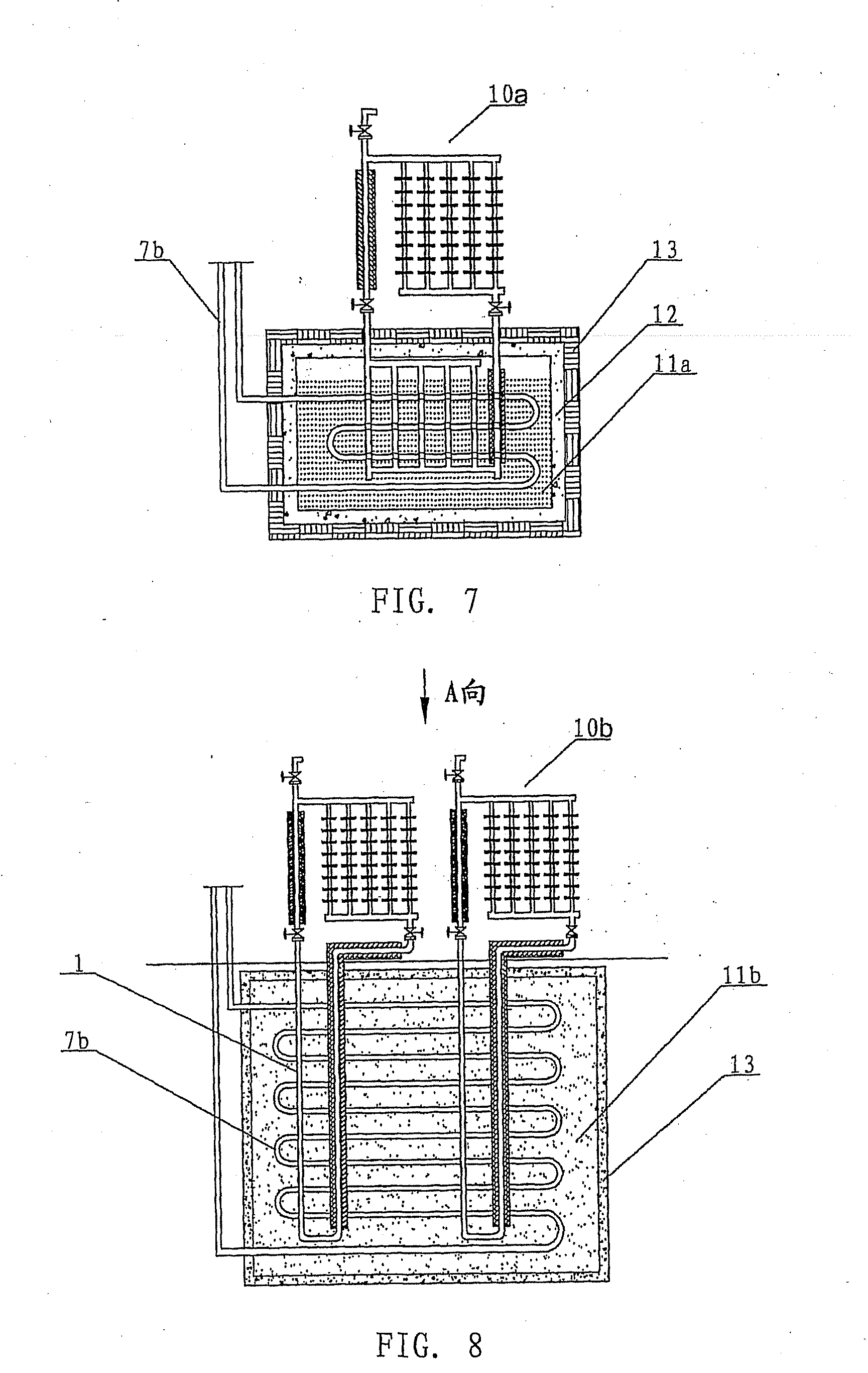
Embodiment 1 of the Energy Storing Device

[0056]As shown in FIG. 7, an energy storing device is composed of a heat tube device 10a and an energy storing medium, which may be liquid-solid phase changing storage material or water 11a. There are a plurality...

embodiment 1

of the Air Conditioning Device and the Building System

[0071]Referring to FIG. 11, an air conditioning device comprises an energy storing device and an terminal loop, the terminal loop comprising an air conditioning terminal, which is a fan coiler 30 positioned inside a building. The energy storing device is a cold storing device, and the energy storing medium is natural soil 11c, in which well holes are drilled deeply in a matrix distribution, especially the distribution in a honeycomb shape with the highest efficiency. The heat tube device of 10e is used in the well holes. An insulating material 13 is disposed on the periphery and the top of the energy storing medium. An insulating layer is also provided outside of an ascending tube 3 and a reflow tube 4. The evaporating part 1 of the heat tube device 10e is under the ground along with the energy storing medium, and the condensing part 2 of the heat tube device is in the ambient atmosphere above the ground. A layer of soil may be f...


PUM


Abstract

The present invention relates to a refrigeration system, associated system of heating and refrigeration, geothermal energy utilizing system, cold storing apparatus, heat storing apparatus and the accessories thereof, and in particular relates to an air conditioning system utilizing natural cold energy, geothermal energy, thermal waste, residual heat and environmental friendly energy.

Description

TECHNICAL FIELD[0001]The present invention relates to a refrigeration system, associated system of heating and refrigeration, geothermal energy utilizing system, cold storing apparatus, heat storing apparatus and the accessories thereof, and in particular relates to an air conditioning system utilizing natural cold energy, geothermal energy, thermal waste, residual heat and environmental friendly energy.BACKGROUND ART[0002]Most of the current refrigerating and energy storing apparatuses and air conditioners utilize a compressor for cycle refrigerating the working substance through compression-expansion. It has the drawbacks of high product energy consumption, high operating cost, unstable operation, complicated maintenance, use of harmful medium, direct and indirect discharge of greenhouse gases and other contamination, noise pollution, strong dependence on electric power, and strong influence on electric power peak load.[0003]The published specification of the Chinese a patent appl...

Claims


Application Information

Patent Timeline
Patent Type & Authority Applications(United States)
IPC IPC(8): F24J3/08F28F1/10F25D23/00F24V50/00
CPCF24F5/0046F24J3/083F24J3/086F25B30/06Y02B10/20Y02B10/24F28D15/0266Y02E10/16Y02B10/40F24F5/0021F24F2005/0025F24F2005/0057Y02E10/125F24T10/30F24T10/15F24T10/40Y02E10/10
Inventor YIN, XUEJUNSONG, JISHENG
Owner YIN XUEJUN
Why Eureka
Try Eureka