Mixing in Wicking Structures and the Use of Enhanced Mixing Within Wicks in Microchannel Devices

a microchannel device and wicking technology, applied in the field of mixing in wicking structures and the use of enhanced mixing within wicks in microchannel devices, can solve the problems of no prior art incorporating a static mixer within a wick, gas escaping through the wick, slow mass transfer, etc., and achieves high heat transfer rate, high efficiency, and durability.

Active Publication Date: 2009-08-27
BATTELLE MEMORIAL INST
View PDF42 Cites 25 Cited by
  • Summary
  • Abstract
  • Description
  • Claims
  • Application Information

AI Technical Summary

Benefits of technology

[0016]In this invention, transport of mass and / or heat is enhanced by mixing within a wick, thus accomplishing a process intensification similar to that which might be accomplished by making thinner wicks and flow channels. Mass transfer in physical processes can be characterized by the Sherwood number,Sh=hmdDwhere hm is the mass transfer coefficient, d is the length-scale for mass transfer, and D is molecular diffusivity. One definition of the mass transfer coefficient is the mass flux (mass flow per unit area) divided by the characteristic mass transfer driving force, which for mass diffusion into a thin film could be the surface concentration minus the bulk mean concentration. For a constant Sherwood number, decreasing the length-scale for mass transfer, d, corresponding to the wick thickness, increases the mass transfer coefficient, hm, thereby enhancing mass transfer and intensifying the process. As described in this invention, a structure can be introduced in the wick that will induce mixing or flow behavior that will enhance the effective diffusivity or the Sherwood number over the transport exhibited by an unstructured wick of the same thickness.
[0021]The liquid in a pore throat has a bubble point that is greater than the maximum pressure difference across the pore throat during operation. This precludes intrusion of gas into the pore throat due to capillary forces (surface tension, wettability, and contact angle dependent). A pore throat can be used to seal the liquid exit, so there should be a seal around the pore throat or the pore throat should cover the exit in order to prevent gas from bypassing the pore throat. The pore throat is preferably very thin to maximize liquid flow through the pore throat at a give pressure drop across the pore throat. Preferably, the pore throat has a pore size that is less than half that of the wick and a thickness of 50% or less than the wick's thickness; more preferably the pore throat has a pore size that is 20% or less that of the wick. Preferably, the pore throat is in capillary contact with the wicking material to prevent gas from being trapped between the wick and the pore throat and blocking the exit.
[0024]In preferred embodiments, wicks are disposed in laminated devices with gas flow channels and wicking regions that are essentially planar in the fluid separation regions. This configuration allows high throughput, rapid and uniform rates of mass and heat transport, and provides a large surface area to volume ratio for high efficiency. In some preferred embodiments, layers are stacked to have separate gas flow channels in 2 to 600 separate layers, more preferably between 4 and 40 separate layers containing gas flow channels. As an alternative to the parallel arrangement, the channels could be connected in series to create a longer flow path. In some preferred embodiments, the gas flow channels and / or liquid flow channels have dimensions of width and length that are at least 10 times larger than the dimension of height (which is perpendicular to net gas flow).
[0026]The invention, in various aspects and embodiments can provide numerous advantages including: rapid mass transport, high rates of heat transfer, low cost, durability, and improved flow properties (combined higher permeability and pumping pressure) in a compact space.GLOSSARY OF TERMS
[0027]An “active mixer” enhances mixing by applying energy such as electrical or sonic energy.
[0039]A “static mixer” is a structure within or adjacent a wick that enhances mixing within the wick. There are many known static mixers for mixing in microchannels, and, in the present invention these may be used in conjunction with a wick to promote fluid mixing in the wick.

Problems solved by technology

As noted in prior work, the wick is preferably not permitted to dry out during operation since this could result in gas escaping through the wick.
This concept however, is undesirable for liquid-gas contact since the available for mass transfer would be small relative to the wicking volume; resulting in undesirable slow mass transfer.
None of the prior art incorporates a static mixer within a wick.

Method used


Image

  • Mixing in Wicking Structures and the Use of Enhanced Mixing Within Wicks in Microchannel Devices
  • Mixing in Wicking Structures and the Use of Enhanced Mixing Within Wicks in Microchannel Devices
  • Mixing in Wicking Structures and the Use of Enhanced Mixing Within Wicks in Microchannel Devices

Examples


Embodiment Construction

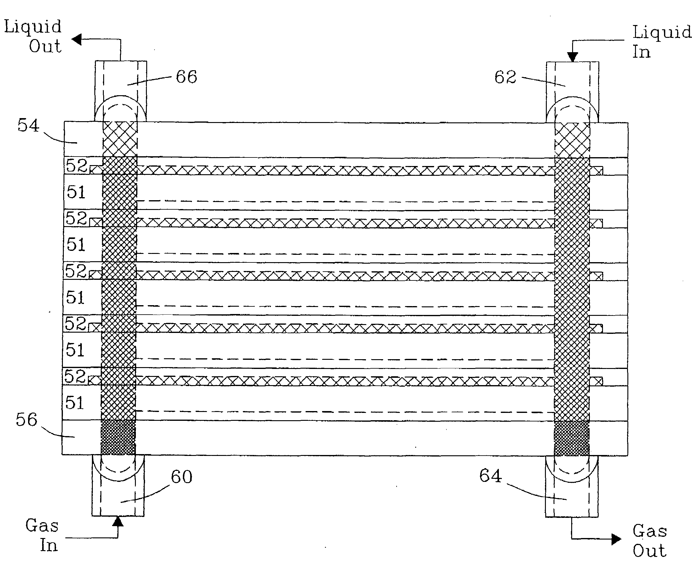
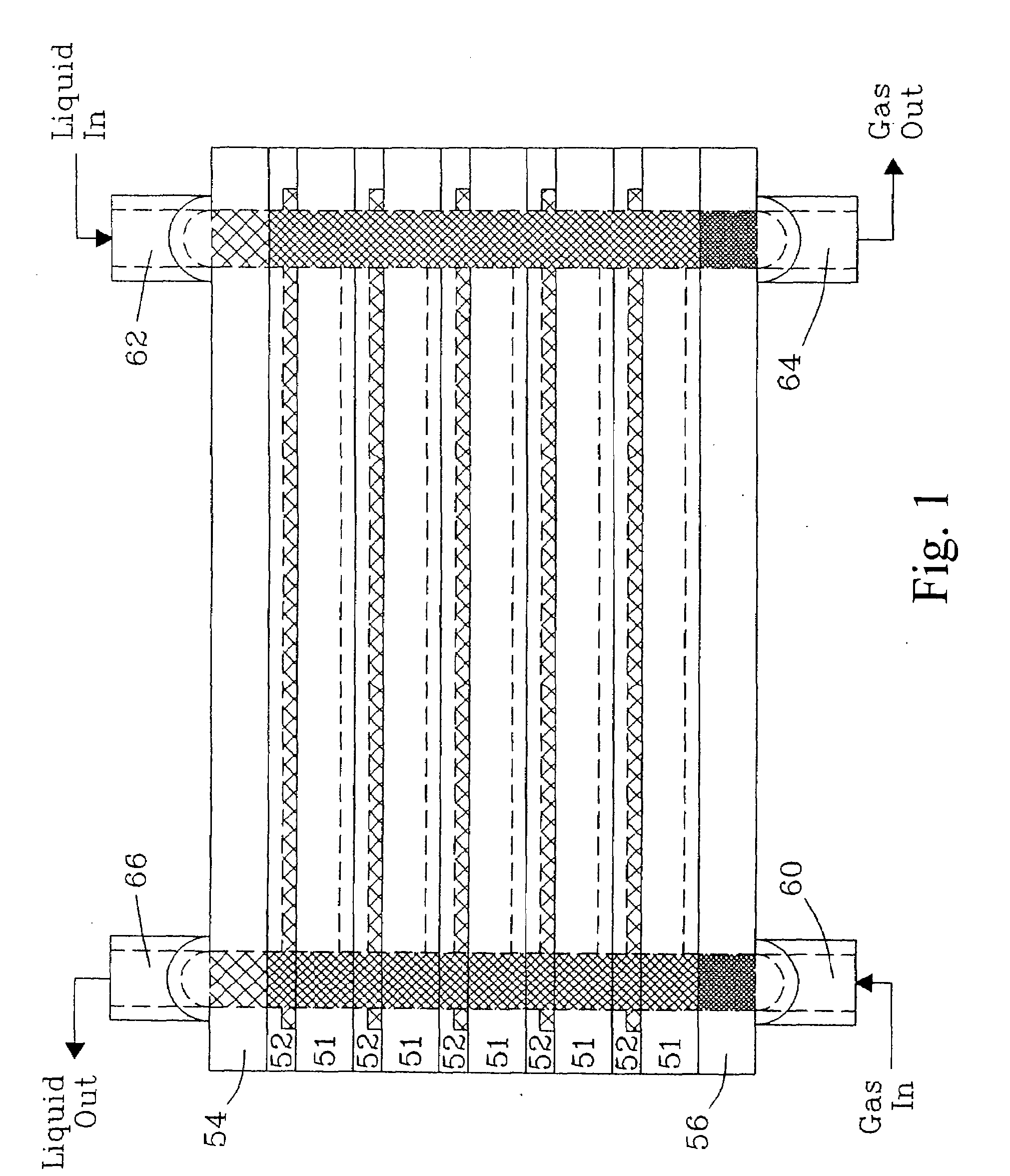
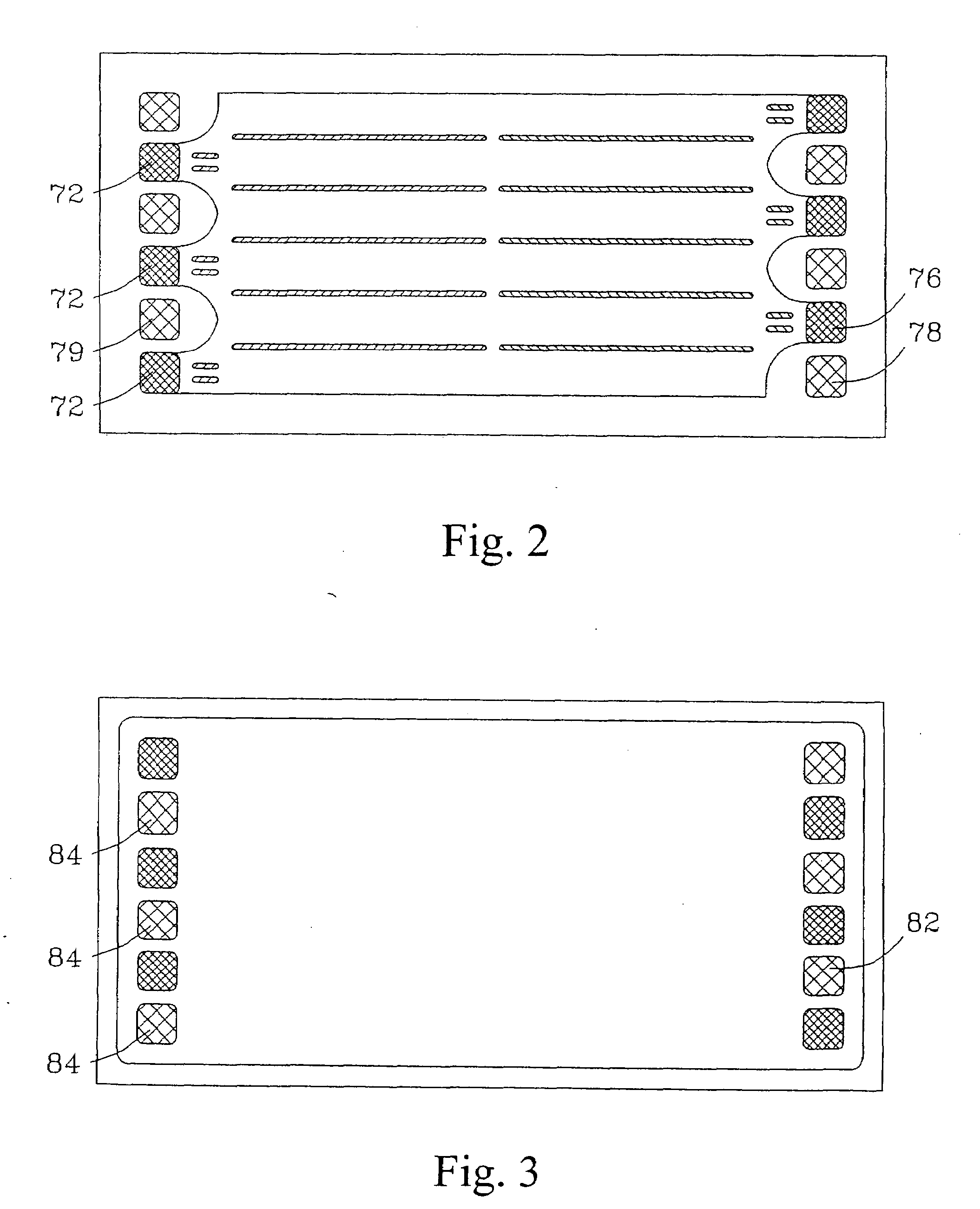
[0050]Devices containing a wick can be made of metals, plastics, ceramic or composite materials. Metal shims (for making a laminated device) can be made by etching; conventional cutting, grinding and machining; electrical discharge machining (EDM); laser machining; stamping or coining; extrusion; molding techniques; or deposition techniques, such as rapid-prototyping, chemical vapor deposition, or electro deposition. Plastic shims can be made using the same techniques or by conventional plastic forming techniques, including injection molding, hot embossing, stamping, casting, and other molding techniques. Ceramic shims could be made using techniques well known for fabricating ceramic parts, including those used in fabricating solid oxide fuel cell elements. The shim material facing the gas channel can be made hydrophobic through coatings, treatment or by the choice of material. The shims can be stacked with wicks installed within the liquid flow channel, either held in loosely by th...


PUM


Abstract

Advanced wicking structures and methods utilizing these structures are described. The use of advanced wicking structures can promote rapid mass transfer while maintaining high capillary pressure through the use of small pores. Particularly improved results in fluid contacting processes can be achieved by enhanced mixing within a wicking layer within a microchannel.

Description

[0001]This invention was made with Government support under Contract DE-AC0676RLO1830 awarded by the U.S. Department of Energy. The Government has certain rights in the invention.FIELD OF THE INVENTION[0002]The present invention relates to processes and devices that utilize wicks within channels.INTRODUCTION[0003]Engineers at Battelle have pioneered the development of wick-containing microchannel devices for processes such as phase separation, condensation with phase separation, gas absorption and desorption, and distillation. Wicks can be incorporated within channels of laminated devices. An embodiment of one such device is illustrated in FIG. 6 of U.S. Pat. No. 6,666,909. A cross-sectional view of this gas / liquid contactor is illustrated in FIG. 1. This contactor has end plates 54 and 56 and alternating shims 51 and 52. T-joint inlets 60 and 62 are for the passage of gas and liquid respectively. T-joint outlets 64 and 66 are for the passage of gas and liquid respectively. A top-do...

Claims


Application Information

Patent Timeline
Patent Type & Authority Applications(United States)
IPC IPC(8): F28D15/00
CPCB01D1/14B01F3/0446B01F5/0619B01F13/0059B01J19/0093B01J2219/00907B01J2219/00835B01J2219/00844B01J2219/00873B01J2219/00889B01J2219/00783B01F23/232B01F25/43161B01F33/30B01J19/00B01D3/00B01F25/00B01F33/00
Inventor STENKAMP, VICTORIA S.TEGROTENHUIS, WARD E.WEGENG, ROBERT S.
Owner BATTELLE MEMORIAL INST
Why Eureka
Try Eureka