
PSA apparatus for producing high-purity hydrogen gas

a high-purity, hydrogen gas technology, applied in chemistry apparatus and processes, separation processes, dispersed particle separation, etc., can solve the problems of difficult to remove co at a level of about 1%, increase the size of the reformer, and prolonged starting time, so as to reduce the size of the equipment and achieve high recovery rate

Active Publication Date: 2009-09-10
KOBE STEEL LTD
View PDF12 Cites 29 Cited by
  • Summary
  • Abstract
  • Description
  • Claims
  • Application Information

AI Technical Summary

Benefits of technology

[0018]In view of such state of the art, it is an object of the present invention to provide a PSA apparatus for high-purity hydrogen gas production which can recover high-purity hydrogen gas at a high recovery rate from a reformed gas (hydrogen-containing gas) produced by a reforming process, for example an autothermal reforming process, and containing, as impurity components, at least CO, CO2, N2 and / or Ar, and can contribute to reducing the equipment size, hence reducing the equipment cost.
[0026]According to the present invention, as the PSA apparatus for producing high-purity hydrogen gas by purifying a reformed gas containing impurities which are at least CO, CO2, N2 and / or Ar, a CO adsorbent capable of selectively adsorbing CO without substantial adsorption of CO2, N2 and / or Ar is used as the adsorbent for removing CO, and a purge gas successively passes the zeolite layer, carbonaceous adsorbent layer and CO adsorbent layer in the operation of regenerating the adsorbent bed. And it consequently becomes possible to realize a reduction in equipment size and prevent the CO2 released from the carbonaceous adsorbent layer from being re-adsorbed in the zeolite layer in the regeneration operation, and furthermore effectively utilize the CO2, N2 and / or Ar released from the zeolite layer for removing N2 and / or Ar and from the carbonaceous adsorbent layer as a part of the purge gas for the CO adsorbent layer, so that high-purity hydrogen gas can be recovered from the hydrogen-containing gas at a high recovery rate.

Problems solved by technology

However, the steam reforming technique requires that the reforming reaction be caused to occur at a high temperature of about 700° C., and since this reforming reaction is an endothermic reaction, there arise problems: external heating becomes necessary, the reformer becomes increased in size and a prolonged period of time is required for starting.
In the conventional hydrogen PSA method, it is difficult to remove CO contained at a level of about 1% at a maximum in the hydrogen gas obtained by reforming a fossil fuel.
And a large amount of an adsorbent (zeolite is generally used) is accordingly required, hence unfortunately the size of the hydrogen PSA equipment (adsorption tower size) becomes very large, and since the rate of recovery of the product hydrogen gas is low, the cost of hydrogen purification rises.
However, these methods have limits in largely reducing the equipment size (adsorption tower size) since the CO gas adsorption capacity of the adsorbent is not sufficient.
As regards the hydrogen recovery rate, improving measures by various methods such as those mentioned above have been investigated, however, any satisfactory measure is not available as yet.

Method used


Image

  • PSA apparatus for producing high-purity hydrogen gas
  • PSA apparatus for producing high-purity hydrogen gas
  • PSA apparatus for producing high-purity hydrogen gas

Examples


first embodiment

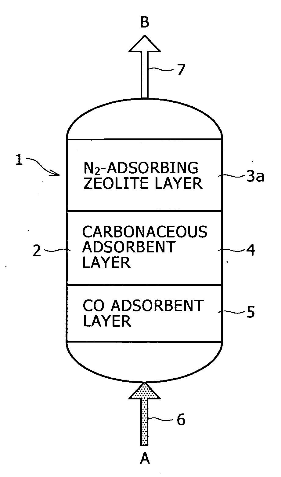
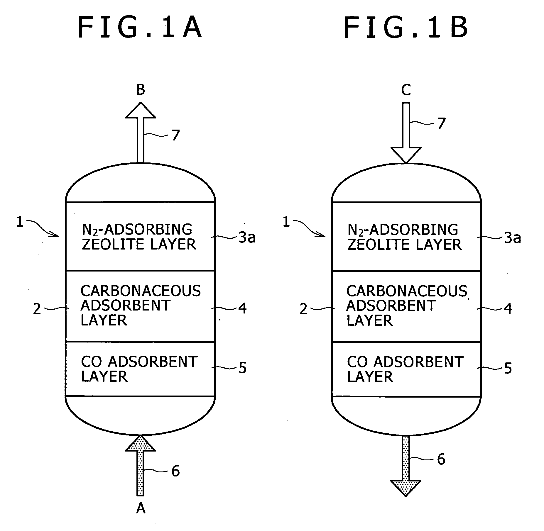
[0037]FIG. 1 is a schematic representation of an adsorption tower in a PSA apparatus according to a first embodiment of the present invention.

[0038]Referring to FIG. 1A, a flow channel 6 for oxydant gas feeding is connected with the lower part of an adsorption tower 1, and a flow channel 7 for treated gas discharging is connected with the upper part thereof. An adsorbent bed 2 is provided in the adsorption tower 1. A CO adsorbent layer 5 for selectively adsorbing CO without substantial adsorption of CO2 and N2, a carbonaceous adsorbent layer 4 for adsorbing CO2, and a adsorbent layer 3a for adsorbing N2 (N2-adsorbing zeolite layer) are successively layered from the lower part of the adsorbent bed 2 to the upper part thereof (namely from the upstream side to the downstream side of the direction of passage of the hydrogen-containing gas A). At the time of regenerating the adsorbent bed 2, a purge gas C successively passes through the adsorbent layer 3a, carbonaceous adsorbent layer 4,...

second embodiment

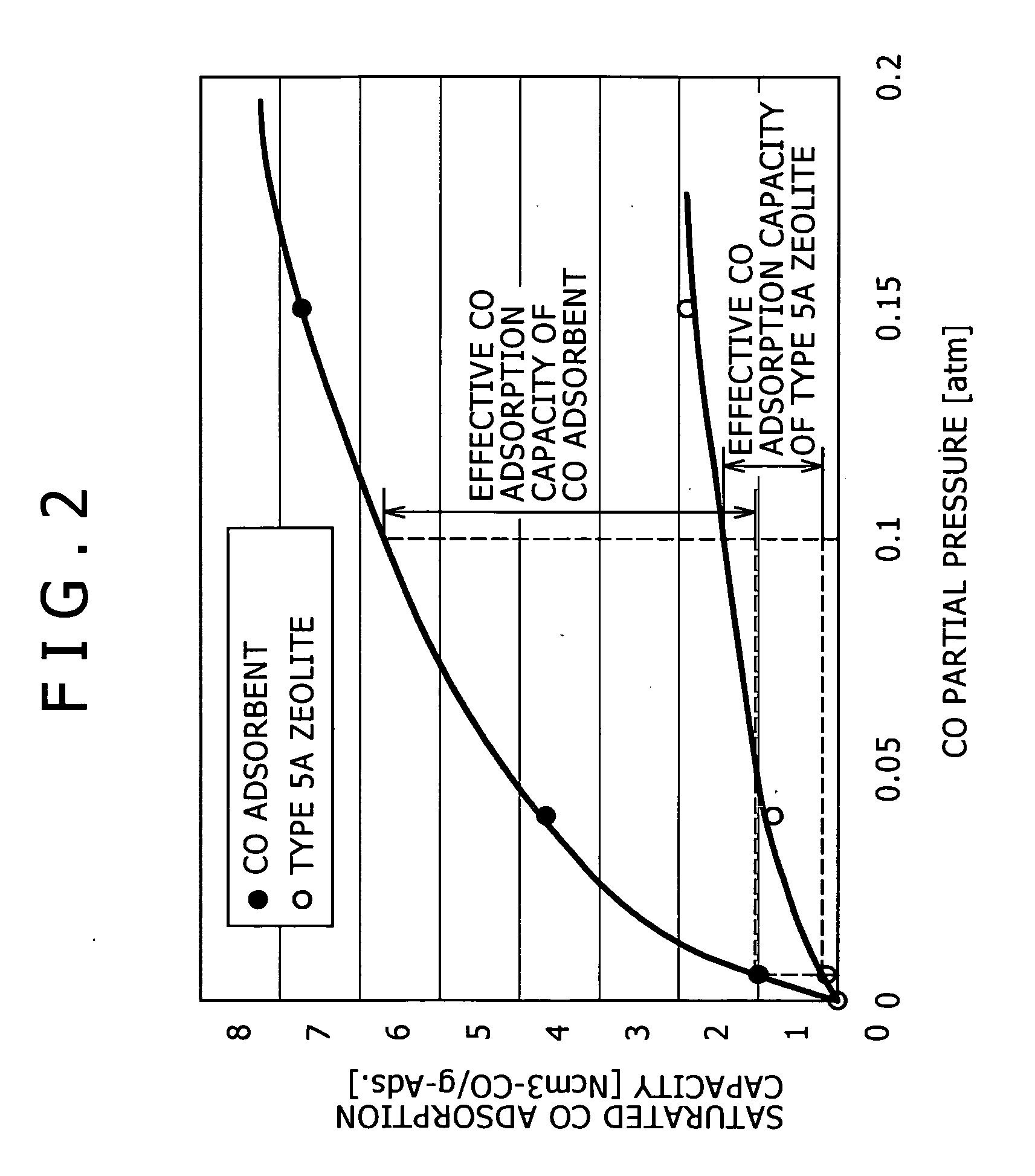
[0049]Therefore, as an embodiment to produce high-purity hydrogen gas without contamination of CO into the product hydrogen gas in the adsorption operation and with a lower degree of vacuum and a smaller purge gas amount in the regeneration operation (second embodiment of the present invention), it is effective to combine CO adsorbent with higher effective CO adsorption capacity and a zeolite for adsorbing CO (CO-adsorbing zeolite) to use.

[0050]An example of adsorbent layers in this second embodiment is shown in FIG. 3. Thus, a CO adsorbent layer 5, a carbonaceous adsorbent layer 4 for adsorbing CO2, a adsorbent layer 3b for adsorbing CO (CO-adsorbing zeolite layer) and a adsorbent layer 3a for adsorbing N2 (N2-adsorbing zeolite layer) are successively layered in the direction from the upstream side to the downstream side of passage of the hydrogen containing gas A. The order of the CO-adsorbing zeolite layer 3b and the N2-adsorbing zeolite layer 3a may be reversed.

[0051]The above-m...

third and fourth embodiments

[0053]The first and second embodiments mentioned above show the PSA apparatus producing high-purity hydrogen gas B from a hydrogen-containing gas A by removing CO, CO2 and N2 by adsorption as examples. Because air contains about 1% by volume of Ar, introducing an oxygen-enriched gas manufactured by an oxygen PSA apparatus or the like from air as material into a reformer makes a reformed gas contain Ar in addition to CO, CO2, and further contain N2 under certain circumstances. And for further increasing the purity of the high-purity hydrogen gas B, it is effective to combine an Ar-adsorbing adsorbent as embodiments in which Ar is removed together with CO and CO2, and N2 is further removed (third and fourth embodiments).

[0054]Examples of adsorbent layers in these third and fourth embodiments are shown in FIG. 4 and FIG. 5, respectively. In FIG. 4 and FIG. 5, an adsorbent layer 3c for adsorbing Ar (Ar-adsorbing zeolite layer) is further layered at the uppermost part within the adsorpti...


PUM

PropertyMeasurementUnit
temperatureaaaaaaaaaa
absolute pressureaaaaaaaaaa

Abstract

A PSA apparatus for high-purity hydrogen gas production is provided which can recover high-purity hydrogen gas at a high recovery rate from a reformed gas (hydrogen-containing gas) produced by a reforming process, for example an autothermal reforming process, and containing, as impurity components, at least CO, CO2, N2 and / or Ar, and can contribute to reducing the equipment size, hence reducing the equipment cost.The PSA apparatus for high-purity hydrogen gas B production by removing CO, CO2 and N2 by adsorption from a hydrogen-containing gas A, comprises an adsorption tower 1; and an adsorbent bed 2 in the adsorption tower, successively including a CO adsorbent layer 5 for selectively adsorbing CO without substantial adsorption of CO2 and N2, a carbonaceous adsorbent layer 4 for adsorbing CO2, and a adsorbent layer 3a for adsorbing N2 in the direction from the upstream side to the downstream side of passage of the hydrogen-containing gas A, wherein, on the occasion of regeneration of the adsorbent bed 2, a purge gas C is passed through in the direction opposite to the direction of passage of the hydrogen-containing gas A.

Description

BACKGROUND OF THE INVENTION[0001]1. Field of the Invention[0002]The present invention relates to a PSA (pressure swing adsorption) apparatus for producing hydrogen gas for fuel cell and, more particularly, to a PSA apparatus improved so that such unnecessary gases such as CO, CH4, CO2, N2 and Ar which are by-products formed during the production of hydrogen gas to serve as a fuel cell energy source (fuel) can be efficiently removed by adsorption and the hydrogen gas production cost can be reduced accordingly.[0003]2. Description of the Related Art[0004]With measures for global warming prevention, it has become an important worldwide task in recent years to escape from the dependence of energy sources on crude oils and, not only in European advanced countries preceding in grappling with environmental preservation problems but also in the United States, Japan and other Asian countries, endeavors to put fuel cells using hydrogen gas as an energy source to practical use have been made a...

Claims


Application Information

Patent Timeline
Patent Type & Authority Applications(United States)
IPC IPC(8): B01D53/04
CPCB01D53/047B01D2253/102B01D2253/108Y02C10/08B01D2257/102B01D2257/502B01D2256/16Y02C20/40
Inventor NAKAO, NOBORUMIURA, SHINICHIYAMASHITA, TAKESHIFUJISAWA, AKITOSHI
Owner KOBE STEEL LTD
Features
  • Generate Ideas
  • Intellectual Property
  • Life Sciences
  • Materials
  • Tech Scout
  • Unparalleled Data Quality
  • Higher Quality Content
  • 60% Fewer Hallucinations
Learn More